This post is older than 2 years and might not be relevant anymore
More Info: Consider searching for newer posts

Moving from nRF51 DK to nRF51822 custom board

Screen Shot 2016-06-16 at 10.27.56 AM.png(/attachment/41972e0db37f912bba4731a3b5ffe839)(/attachment/0838bef738e72c89e2a9af90d6e3f640)(/attachment/a62ce68db8c9d23b285a9f94a5c9beac)I have been developing on the nRF51 DK for some time with no trouble. I am using nRFgo studio to erase and flash softdevice s130. I am using uVision for development and flashing applications.

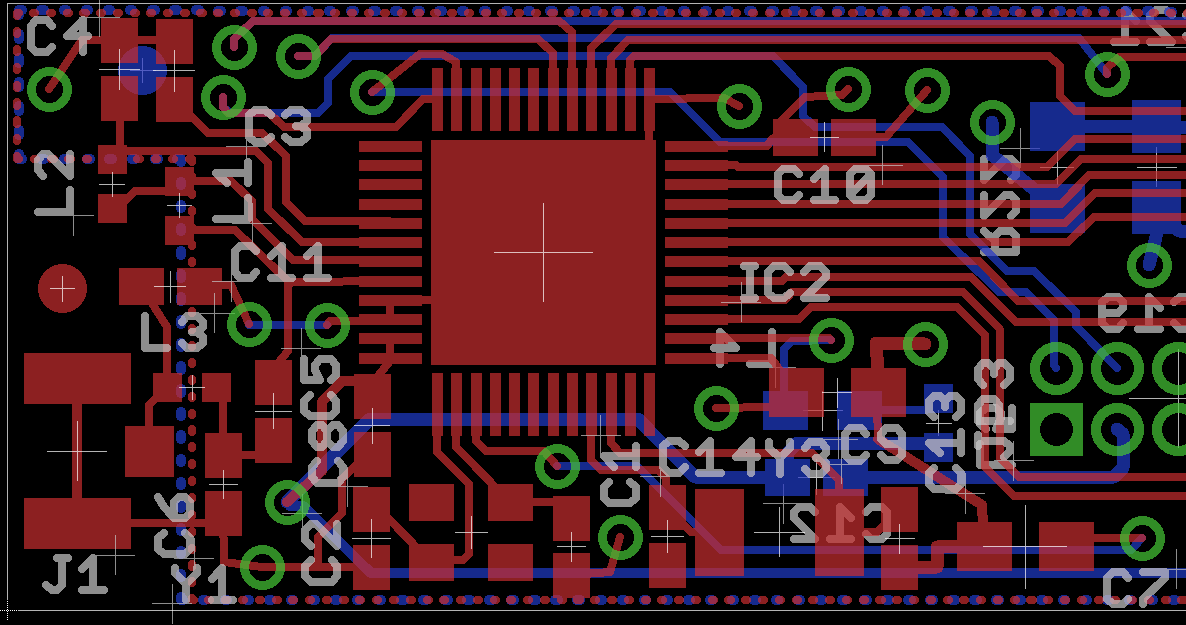
Now, I have a custom board with an nRF51822 QFAC on it and cannot seem to get the BLE module working. The schematic was basically copied from the nRF51 DK and implemented on our custom board. I am programming the custom board through the JLink on the nRF51 DK. When I open nRFgo studio, I am able to see the device (nrf51822 as opposed to nrf51422 for the dk) and program the device. I am also able to program the device from uVision, but only if the the chip has been erased in nRFgo Studio first.

I am confident that the code is loading to the device, as I am able to toggle a GPIO pin and step through he code using the JLINK debugger. My issue arises when my application attempts to interact with the ble stack. The device hangs upon trying to initialize anything related to ble.

My thoughts on potential causes:

  1. the softdevice could be getting loaded into the incorrect place in memory. Do I need to change any linker setting to get this to work? Are the nrf51422 and nrf51822 memory maps compatible? Is there an issue loading from nrfgo studio compared to uvision.

  2. When looking at the 16MHz crystal pins on the processor, I cannot find a valid sin wave. I am able to run code on the device, but I am not sure if this requires the 16MHz clock or just the internal RC oscillator. I have my settings such that the NRF_CLOCK_LFCLKSRC is set to use the internal RC oscillator.

  3. Are there other configurations or target settings that I need to do in order to switch from the DK to a custom nRF51822 board?

Thank you!

  • FormerMember
    0 FormerMember

    1) Code running on nRF51422 (except for ANT), should work without any changes on nRF51822 as well.

    2) If you are not sure if the 16 MHz crystal works correctly or not, could you verify that the crystal has been correctly mounted on the PCB, not shifted by 90 degrees for instance? The 32 kHz internal RC oscillator uses the 16 MHz crystal to get the correct frequency.

    3) No, there shouldn't be other configurations that you need to set. Since you have a nRF51822 QFAC chip, your chip should have the same amount of flash/RAM as the chip on the DK, 256 kB flash and 32 kB RAM.

    Could you test one of the examples from the SDK (if that is not what you already are doing), just to make sure that the BLE initialization is being done correctly.

    Does the code with the NRF_CLOCK_LFCLKSRC setting work on your DK?

  • Hi Kristen,

    Thanks for the reply! Your answers are consistent with what we thought originally. To further address your points:

    1. we actually swapped an nRF51822 with an nRF51422 on our custom HW and they fail in the same spot. Specifically, at line 285 in softdevice_handler.c, err_code = sd_softdevice_enable(p_clock_lf_cfg, softdevice_fault_handler); This looks like the first time the initialization actually makes a call to softdevice compiled code.

    2. We have double checked the crystal and it seems to be mounted correctly. We are not able to see a sine wave on the crystal output, but when removing the crystal, the chip does not function at all.

    3. that's what I thought. Also fits with the fact that both nRF51422 QFAC and nRF51822 QFAC are experiencing the same problem.

    We have tried numerous examples, and none have been able to initialize BLE. I think our problem is with interacting with the softdevice.

  • UPDATE: after changing clock settings to the following I am able to initialize everything (or at least the program now runs through to the infinite loop in main).

    #define NRF_CLOCK_LFCLKSRC      {.source   = NRF_CLOCK_LF_SRC_RC,/*NRF_CLOCK_LF_SRC_XTAL,*/      
                                                         .rc_ctiv       = 16, 
                                                         .rc_temp_ctiv  = 16,
                                                         .xtal_accuracy = NRF_CLOCK_LF_XTAL_ACCURACY_20_PPM}
    

    Unfortunately, the device is still not advertising such that my phone can see. I have put in multiple print statements that indicate that the device is advertising; calls to sd_ble_gap_adv_start() returns NRF_SUCCESS

    Any ideas?

  • FormerMember
    0 FormerMember in reply to FormerMember

    Could you show what the layout of the chip/antenna part looks like? If you want to keep it confidential, you can create a new support case on www.nordicsemi.com and refer to this thread.

  • I added an image of the layout to the original post. I tried to add the schematic as an attachment as well. let me know if it got through.

Related