This post is older than 2 years and might not be relevant anymore
More Info: Consider searching for newer posts

Tuning provisions for Meander Antenna?

Hi, i am designing a board using balun in it. Also, i am going to use meander antenna of nordic dongle(reference image is attached). As i can see, there is no RF coplaner waveguide strip but there are RF traces connecting C6, C14, R17, L4. So, my questions are:

  1. To connect C6, C14, R17, L4, do i need to calculate the trace width for 50 ohm impedance (RF connecting traces in dongle doesn't seem to have impedance of 50 ohm.)?

  2. As per my understanding, in order to tune the antenna, i need to put the SMA coaxial connector before pi network or solder coaxial cable after cutting the trace before pi network. But i don't see any place for that in nordic Dongle design. How did nordic guys do that? i have following assumptions/ questions:

    a. were these pi network footprints added to subsequent prototype after tuning done for previous one as there is no extra place for tuning connector or cable?

    b. Even, if i provide place for a SMA coaxial connector before the pi network footprints, what would happen to the left space after removing SMA coaxial connector (adding trace of 50 ohm would take up space)? Can i move pi network close to balun (RF part) after removing coaxial connector as pi network is close to C6 in Nordic Dongle?

  3. Do i really need pi network to tune this meander antenna of dongle or a shunt capacitor would be enough?

Note: I am new to all this stuff, so please spare me for my wrong assumptions/ questions and also, don't forget to correct me. There is not sufficient knowledge related to antenna tuning PROCEDURE for a layman like me. It'd be great, if nordic Guys would come up with simple and step by step guide for tuning (nWP-017 isn't enough).
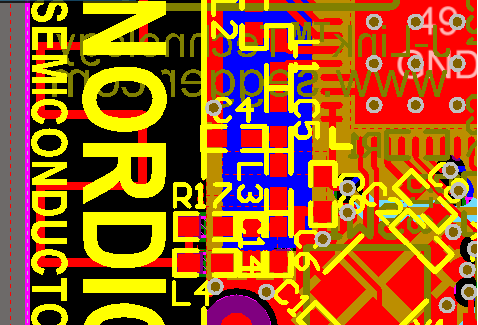
image description

  • Hi,

    1. Connecting traces between the lumped components of the output match do not need to be designed for 50 ohm, just make sure to follow the reference layout closely. After the final component in the output match, in your case the balun output, a microstrip or coplanar waveguide should be employed to connect to the antenna, if it has to be situated away from the chip. These have to be calculated. For the antenna itself the most important is that it is resonant for the design frequencies, the width of the antenna trace determines the bandwidth of the antenna.

    2. Adjust the electrical length of your VNA measurement cable so that it is at the end of an open ended coaxial cable, by increasing/decreasing the electrical delay until it reaches the far right side of the smith chart (infinite impedance). Next you will want to solder the center conductor of this cable at the start of your pi network, ie. at the start of the antenna trace. Remember to cut the trace on the right behind where you place your cable.

    3. You can copy the meander antenna from the dongle layout, but make sure to add a few mm (easier to remove than to add) so that you have some margin. It is likely that your antenna will resonate differently than the one on the dongle as they are highly dependent on ground plane. Set your network analyzer to SWR mode and cut until you observe a dip (resonant point) in SWR at the desired frequency. Once you are satisfied switch to smith chart view for S11, if the desired frequency is fairly close to G=1 circle then your pi network will consist of a simple shunt capacitor. In other cases it may be far from G=1 and a full PI network is needed, the only way to know for sure is to measure. This is why you should add room for a full PI network on your PCB.

    Best regards,

    Øyvind

Related