This post is older than 2 years and might not be relevant anymore
More Info: Consider searching for newer posts

PCA10031 antenna matching

Our BLE product uses a meander PCB antenna similar to PCA10031. It works actually quite fine, but a question pops up when it comes to tuning.

Antenna matching design in the PCA10031 module looks a bit strange. Fragment of the matching nepwork

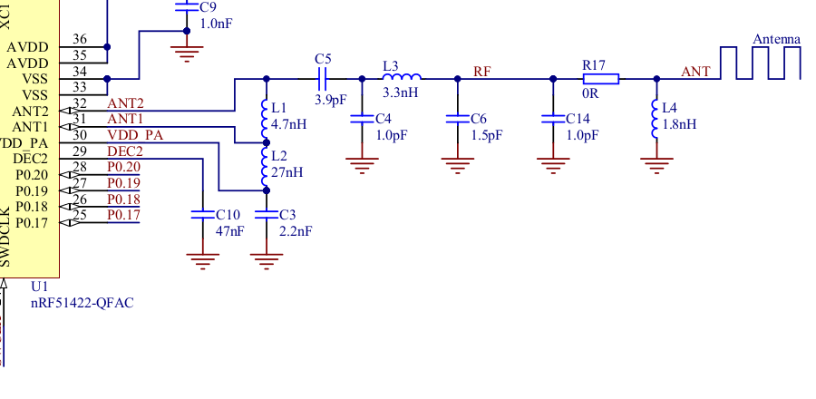
I do not fully understand the idea of having C14 in parallel with L4. At 2.4 GHz these two could be replaced by an equivalent ~3 nH shunt. Why it was designed so? Does it (maybe) have something with extra filtration of 4.8 GHz harmonic or some other things I do not grokk?

  • It is not correct that C14 and L4 would evaluate to 3nH at 2.4GHz just because mathematically it seems true. Even at a relatively low frequency such as 2.4GHz, the phase separation of R17 and the ground via placement would be very significant. As a example, it is not uncommon to see a chain of several caps in row separated by a few mm each time. While it may look like it works as one cap, it does not and this chain will very effectively transform a low impedance to a high impedance.

    In the case of your matching network, since the 51422 doesn't have on chip harmonic filtering, I would guess that the intention was a match designed as a low pass network to filter harmonics. At 2.4GHz it provides a match to 50ohms for the 51422 and above 2.4GHz looks more and more like a low pass filter. In addition at 2.4GHz, C14 and L4 might just resonate becoming an open circuit then above 2.4 they become a shunt (ie, low pass network).

  • C14/L4 resonates at > 3 GHz.

    Meander antenna matches quite easy with just a single shunt, thinking 2.4GHz I see no reason of doing tricks with distributed network here. It might be a harmonics filtering network. The biggest question then is do we need to keep it this way :)..

  • While the meander might match easily, the 51422 most likely will not. Matches go both ways.

Related