For my application I use a RTC. For now without SD and based on SDK 11.0. Later I will implement it in an application with BLE. My device is a Raytac module with a nRF52832 on it. The module is connected with the RTC DS1307.
I think that I had success with write to the RTC. Because I get an ACK(NRF_DRV_TWI_EVT_DONE) back after the sequences. But I wont get anything when I try to read the registers of the RTC.
I assume that when I get a NRF_DRV_TWI_EVT_DONE this means, that the TX was successful and this is an ACK?
Does anyone have experience with the DS1307? What should I do, to get the data from the RTC?
And how many bytes do I have to expect to recieve?
Here my code:
#define SCL_PIN 15
#define SDA_PIN 14

#define SLAVE_ADRESSE_W				0x68

#define SLAVE_ADRESSE_R				0x69

#define SEKUNDEN_ADRESSE			0x00
#define MINUTEN_ADRESSE				0x01
#define STUNDEN_ADRESSE				0x02
#define TAG_ADRESSE					0x03
#define DATUM_ADRESSE				0x04
#define MONAT_ADRESSE				0x05
#define JAHR_ADRESSE				0x06

#define WERT_ADRESSE				0x05

uint8_t data[3];							//Array für Daten(3Bytes)


void DS1307_set_mode(void)
{
  ret_code_t err_code;
  uint8_t reg[2] = {SEKUNDEN_ADRESSE, WERT_ADRESSE};
  err_code = nrf_drv_twi_tx(&m_twi_driver, SLAVE_ADRESSE_W, reg, sizeof(reg), false);
  APP_ERROR_CHECK(err_code);

  while(m_set_mode_done == false);
}

void read_data()
{
  uint8_t higher_byte;						//Variabel für höcherwertiges Byte aufsetzen
  uint8_t lower_byte;							//Variabel für niederwertiges Byte aufsetzen
  higher_byte 	= data[0];
  lower_byte	= data[1];
}

void twi_handler(nrf_drv_twi_evt_t const * p_event, void * p_context)
{
    ret_code_t err_code;

    switch(p_event->type)
   {
        case NRF_DRV_TWI_EVT_DONE:
        if ((p_event->type == NRF_DRV_TWI_EVT_DONE) && (p_event->xfer_desc.type == NRF_DRV_TWI_XFER_TX))
        {
          nrf_drv_twi_rx(&m_twi_driver, SLAVE_ADRESSE_R, (uint8_t*)data, sizeof(data));
          APP_ERROR_CHECK(err_code);
          read_data();
        }

        if ((p_event->type == NRF_DRV_TWI_EVT_DONE) && (p_event->xfer_desc.type == NRF_DRV_TWI_XFER_RX))
        {
	      nrf_drv_twi_rx(&m_twi_driver, SLAVE_ADRESSE_R, (uint8_t*)data, sizeof(data));
          APP_ERROR_CHECK(err_code);
          read_data();
        }
        break;
        default:
        break;
    }
}

void twi_init (void)
{
    ret_code_t err_code;

    const nrf_drv_twi_config_t twi_mma_7660_config = {
   .scl                = SCL_PIN,
   .sda                = SDA_PIN,
   .frequency          = NRF_TWI_FREQ_100K,
   .interrupt_priority = APP_IRQ_PRIORITY_HIGH
    };

    err_code = nrf_drv_twi_init(&m_twi_driver, &twi_mma_7660_config, twi_handler, NULL);
    APP_ERROR_CHECK(err_code);

    nrf_drv_twi_enable(&m_twi_driver);
}

int main(void)
{
    twi_init();
    DS1307_set_mode();

     while(true)
     {

     }
}
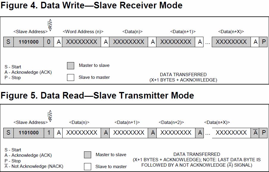
From the Datasheet:
Depending upon the state of the R/W bit, two types of data transfer are possible:
-
Data transfer from a master transmitter to a slave receiver. The first byte transmitted by the master is the slave address. Next follows a number of data bytes. The slave returns an acknowledge bit after each received byte. Data is transferred with the most significant bit (MSB) first.
-
Data transfer from a slave transmitter to a master receiver. The first byte (the slave address) is transmitted by the master. The slave then returns an acknowledge bit. This is followed by the slave transmitting a number of data bytes. The master returns an acknowledge bit after all received bytes other than the last byte. At the end of the last received byte, a “not acknowledge” is returned.
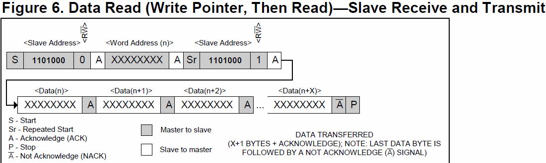
The master device generates all the serial clock pulses and the START and STOP conditions. A transfer is ended with a STOP condition or with a repeated START condition. Since a repeated START condition is also the beginning of the next serial transfer, the bus will not be released. Data is transferred with the most significant bit (MSB) first.