

Here is an example of a hardware setup to measure the voltage on a Lithium battery with a voltage divider on nRF52. The Lithium battery typically has a voltage range of 2.7 - 4.2 V and we (Nordic) recommend that you divide the battery voltage with two resistors and possibly a capacitor (more on that later)
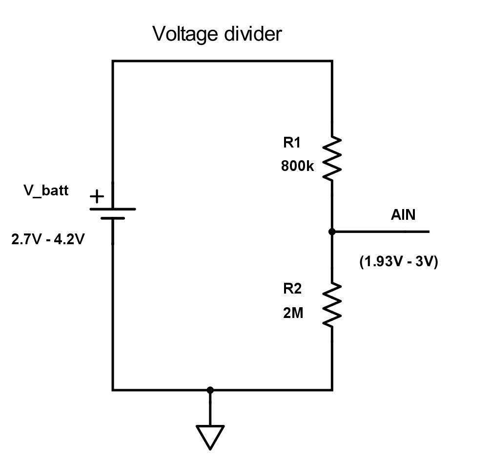
To reduce the leakage current through the voltage divider to the minimum, we want the total resistance to be as high as possible. Therefore, we choose R1 to be 800 KΩ. This is the maximum source resistance we can have if we use an acquisition time of 40 us, see here.
We also want R2 to be large. R2 should be chosen such that the input voltage does not exceed Vdd when the battery is full (4.2 V). In this example Vdd is 3.3 V, so we choose R2 to be 2 MΩ which will give 3 V at AIN when battery is 4.2 V. With a gain of 1/5 we can use the internal reference at 0.6 V.
The leakage current with this configuration will be:
4.2 V / 2.8 MΩ = 1.5 uA
If you are using lower Vdd, R2 will have to be smaller and the leakage current will increase.
Usable ADC resolution
If we assume that the voltage range of the Lithium battery is 2.7 V - 4.2 V, i.e. 2.7 V when empty and 4.2 V when fully charged, then the voltage range on the ADC AIN input pin is:
- Maximum voltage: 4.2 V * (2 M/(0.8 M+2 M)) = 3 V
- Minimum voltage: 2.7 V * (2 M/(0.8 M+2 M)) = 1.93 V
- ADC value at 4.2 V – 12 bit setup: 3 V * (1/5) / 0.6 V * 4095 = 4095
- ADC value at 2.7 V - 12 bit setup: 1.93 V * (1/5) / 0.6 V * 4095 = 2634
- Usable ADC resolution - 12 bit setup: 4095 - 2634 = 1461
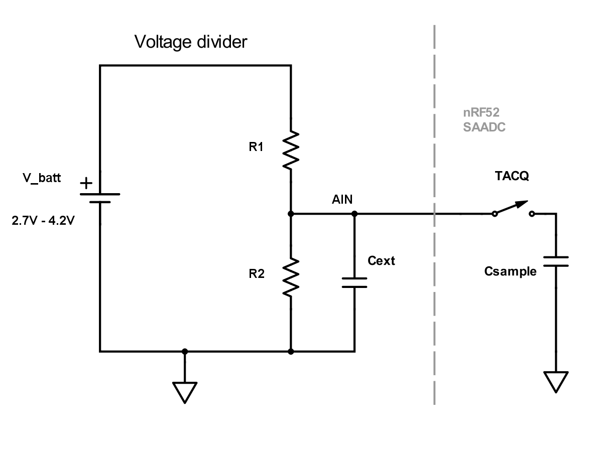
Using capacitor
Using a capacitor has several advantages over a pure resistive divider. The input will be more resistant to noise, you can use higher values on the voltage divider which will lead to less leakage current and you can set down the acquisition time.
Choosing the capacitor value
At the start of the sampling (when TACQ switch closes) there will be a voltage drop. The capacitor value should be high enough such that this voltage drop is small. The SAADC voltage the moment the sampling starts is about:
Vsaadc = Vain * (Cext – Csample) / Cext
We can say that we want the voltage drop to be equal to the voltage corresponding to 1LSB. If we use 12 bit resolution Cext can be calculated like this:
Vsaadc / Vain = 1 – 1 / 2^12
1 - 1 / 2^12 = (Cext – Csample) / Cext
Cext - 2^-12 * Cext = Cext - Csample
Cext = Csample * 2^12
If we say that Csample is 2.5pF (maximum according to Product Specification), then Cext will be:
Cext = 2.5 pF * 2^12 ~= 10nF
With this large external capacitor, we can also set down the acquisition time since the sampling capacitor (Csample) takes less time to charge up. Acquisition time can be set to the minimum, 3us. This will in addition reduce the current consumption as the SAADC spends less time sampling.
Choosing the sampling frequency
Over time the SAADC input can be seen as a resistor with the value 1/(f*C). The sampling frequency should be chosen such that the saadc input impedance is much larger than the resistor values in the voltage divider. The saadc input impedance is:
Rinput = 1 / (fsample * Csample)
If we choose a sampling frequency of say 1 second, the input impendance will be:
Rinput = 1 / (1 * 2.5*10^-12) = 400GOhm
Example
Based on these calculations we can for example use these values: R1 = 4MOhm, R2 = 10MOhm, Cext = 10nF. Then the leakage current will maximum be:
4.2V / (10MOhm + 4MOhm) = 300nA

Top Comments