This discussion has been locked.
You can no longer post new replies to this discussion. If you have a question you can start a new discussion

How to use I2C on nRF52840 Dongle ?

Hi,

I am not sure whether there is I2C pins on nRF52840 Dongle board as based on the Adafruit Feather nRF52840 Express the pin is P0.11 and P0.12 as shown below:
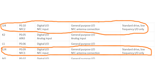
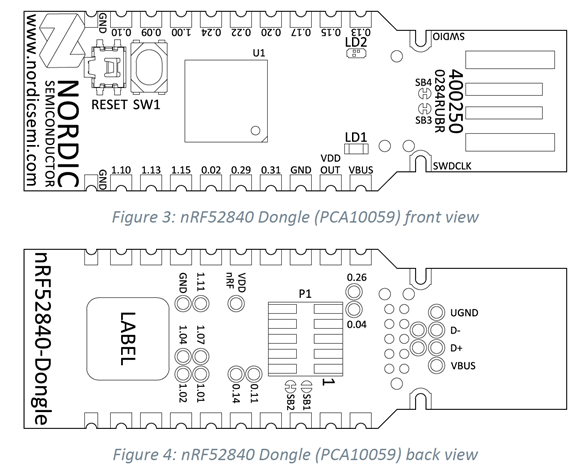
SCL 0.11 and SCK 0.14 are at the back of the nRF52840 Dongle but SDA 0.12 is missing from the nRF52840 Dongle board.


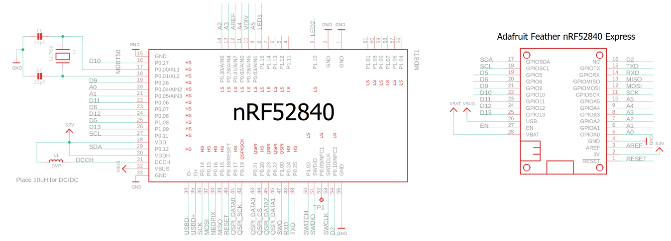
There is a Youtube link shown the use of I2C display with nRF52840 Dongle but lacking explanation.

https://www.youtube.com/watch?v=vJUrG41tYFw


I am new to Nordic nRF52840 Dongle board and trying to support it under Arduino platform, but found out many missing important protocol pins.
Otherwise, I will just use Adafruit Feather nRF52840 Express.

May I know is the pin number held on Nordic nRF52840 (eg. 0.11) and on the schematic diagram (SCL P0.11) from Adafruit nRF52840 Express the same ?

Please advise.

  • I haven't used Arduino (well, except some time ago on an Arduino board) so I can't really help you there, but the nRF52840 lets you use just about any pins for just about any peripherals.  You just set them during the peripheral configuration and off you go.  Maybe whatever Arduino does to interface with the board allows you to put in a custom configuration?

  • Are you using the twi library or peripheral… if so the pins can be easily programmed to use almost any pins you wish. I recommend either showing us a code snippet as it will be easier to interpret or you can also look at this YouTube channel I found it very helpful during my implementations sumair’s embedded electronics

  • Hello Ricky,

    The nRF52840 Dongle has 15 GPIOs in addition to the ground, power, and SWD connections along the castellated edges as we can see from the device picture (Nordic Semiconductor Infocenter).

    There are SWD interfaces on the back side of the dongle, these are the connection points (P1 and J2 connector) for the SWD interface.

    There are no dedicated TWI pins in the nRF52840 devices. Any GPIO pin can be used for any function with any digital peripheral. You just need to configure the peripheral to use the correct pins, typically via the driver configuration. So, theoretically it is possible to use any pin as 12C. you can look at this link . Nordic Semiconductor Infocenter.

    I have added schematic diagram of nRF52840 dongle, so you can compare it with the schematic diagram of Adafruit nRF52840 by yourself.PCA10059_Schematic_And_PCB.pdf

    Please let us know if you have more queries to ask.

    Best Regards,

    Kazi Afroza Sultana

  • hi Kazi,

    I am new to Nordic product, merely testing at high level using Arduino framework programming.

    "You just need to configure the peripheral to use the correct pins, typically via the driver configuration. "
    - Can you show me the tutorial videos how to do this in details and can it apply to Arduino IDE or PlatformIO IDE ?

    I came from a software developer background, and not intending to write bare metal code but merely using Arduino framework will do.

    Please advise.

  • Hello Ricky,

    We do not have any examples with Arduino code. 

    I would like to refer you to use Nordic nRF5 SDK ( for downloading the nRF5 SDK follow this link: http://developer.nordicsemi.com/nRF5_SDK/nRF5_SDK_v17.x.x/)  and can look at the TWI example (https://infocenter.nordicsemi.com/index.jsp?topic=%2Fcom.nordic.infocenter.sdk5.v15.0.0%2Ftwi_sensor_example.html) . There are two twi examples which you should be able to use as reference, e.g. \twi_scanner and \twi_sensor, the pins used by twi is controlled by defines and can be changed where you see best fit:

    void twi_init (void)
    {
    ret_code_t err_code;

    const nrf_drv_twi_config_t twi_lm75b_config = {
    .scl = ARDUINO_SCL_PIN,
    .sda = ARDUINO_SDA_PIN,

    .frequency = NRF_DRV_TWI_FREQ_100K,
    .interrupt_priority = APP_IRQ_PRIORITY_HIGH,
    .clear_bus_init = false
    };

    err_code = nrf_drv_twi_init(&m_twi, &twi_lm75b_config, twi_handler, NULL);

    APP_ERROR_CHECK(err_code);

    nrf_drv_twi_enable(&m_twi);

    }

    Regarding pin selection: One thing I would like to add (what I did not mention in my previous reply) regarding using of GPIO pin (any) as 12C. It is recommended not to select the pin close to the radio ( these are marked as low frequency I/O, you can see in the pinout documentation).  But if there is no plan to communicate simultaneously then it should not be a problem. you can find pin assignment here in this link Nordic Semiconductor Infocenter

    You also look at this tutorial to start with nRF52840 dongle https://devzone.nordicsemi.com/guides/short-range-guides/b/getting-started/posts/nrf52840-dongle-programming-tutorial . It was written on 2018 and still relevant. 

    Hope it helps.

    Best Regrads,

    Kazi Afroza Sultana

Related