This discussion has been locked.
You can no longer post new replies to this discussion. If you have a question you can start a new discussion

How to use I2C on nRF52840 Dongle ?

Hi,

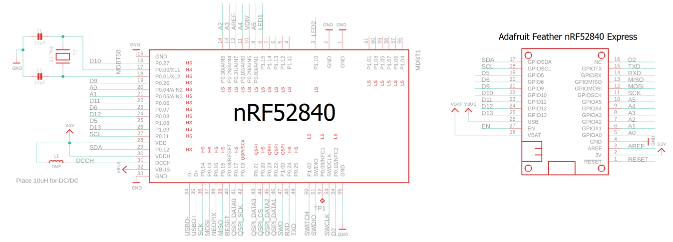
I am not sure whether there is I2C pins on nRF52840 Dongle board as based on the Adafruit Feather nRF52840 Express the pin is P0.11 and P0.12 as shown below:
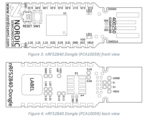
SCL 0.11 and SCK 0.14 are at the back of the nRF52840 Dongle but SDA 0.12 is missing from the nRF52840 Dongle board.


There is a Youtube link shown the use of I2C display with nRF52840 Dongle but lacking explanation.

https://www.youtube.com/watch?v=vJUrG41tYFw


I am new to Nordic nRF52840 Dongle board and trying to support it under Arduino platform, but found out many missing important protocol pins.
Otherwise, I will just use Adafruit Feather nRF52840 Express.

May I know is the pin number held on Nordic nRF52840 (eg. 0.11) and on the schematic diagram (SCL P0.11) from Adafruit nRF52840 Express the same ?

Please advise.

Parents
  • Hello Ricky,

    The nRF52840 Dongle has 15 GPIOs in addition to the ground, power, and SWD connections along the castellated edges as we can see from the device picture (Nordic Semiconductor Infocenter).

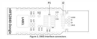
    There are SWD interfaces on the back side of the dongle, these are the connection points (P1 and J2 connector) for the SWD interface.

    There are no dedicated TWI pins in the nRF52840 devices. Any GPIO pin can be used for any function with any digital peripheral. You just need to configure the peripheral to use the correct pins, typically via the driver configuration. So, theoretically it is possible to use any pin as 12C. you can look at this link . Nordic Semiconductor Infocenter.

    I have added schematic diagram of nRF52840 dongle, so you can compare it with the schematic diagram of Adafruit nRF52840 by yourself.PCA10059_Schematic_And_PCB.pdf

    Please let us know if you have more queries to ask.

    Best Regards,

    Kazi Afroza Sultana

Reply
  • Hello Ricky,

    The nRF52840 Dongle has 15 GPIOs in addition to the ground, power, and SWD connections along the castellated edges as we can see from the device picture (Nordic Semiconductor Infocenter).

    There are SWD interfaces on the back side of the dongle, these are the connection points (P1 and J2 connector) for the SWD interface.

    There are no dedicated TWI pins in the nRF52840 devices. Any GPIO pin can be used for any function with any digital peripheral. You just need to configure the peripheral to use the correct pins, typically via the driver configuration. So, theoretically it is possible to use any pin as 12C. you can look at this link . Nordic Semiconductor Infocenter.

    I have added schematic diagram of nRF52840 dongle, so you can compare it with the schematic diagram of Adafruit nRF52840 by yourself.PCA10059_Schematic_And_PCB.pdf

    Please let us know if you have more queries to ask.

    Best Regards,

    Kazi Afroza Sultana

Children
No Data
Related