Pin Configuration for PWM

Hi,

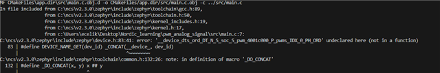
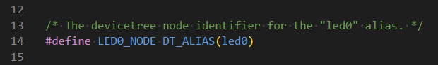
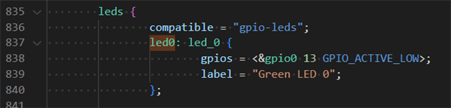
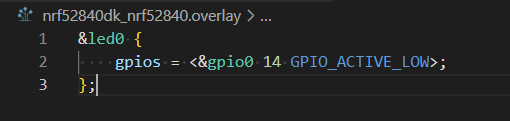
I am quite new to Nordic boards. I need to figure out how to output PWM signal to GPIO pins. I went through Nordic's tutorial to get started. However, I could not figure out how to use overlays and perform pin assignment. What I want to do is assign PWM0 to gpio0 14 and import the driver in my main code. I always get same error shown in the image.  Any hep appreciated. Thank you.

Parents
  • Hello,

    Thank you for contacting DevZone at NordicSemi.

    To better understand the DTS and overlay files, I recommend you go through DevAcademy NCS Fundamental Lecture-2 & 3 that discuss about Device Tree Structure (DTS), Driver Model, and Overlays (with examples).

    As an example, consider following (you may try as per your board and needs):
    1. Build and flash blinky sample on nrf52840 DK and observe that LED1 (top left led on the DK) starts blinking
    2. As the main code uses led0, Open compiled device tree and look node label led0

    you will find that the led0 is connected to the gpio0 pin 13

    3. To change pin assignment for le0, we need to do so in an overlay file. Therefore, I created file called nrf52840dk_nrf52840.overlay (file name need to be specific as per your board) and assigned it to pin number 14

    4. After building and flashing, you will see that now LED2 (top right led on the DK) starts blinking

    You may explore pwm_blinky sample afterwards and try to incorporate the required changes.

    Regards,

    Naeem 

Reply
  • Hello,

    Thank you for contacting DevZone at NordicSemi.

    To better understand the DTS and overlay files, I recommend you go through DevAcademy NCS Fundamental Lecture-2 & 3 that discuss about Device Tree Structure (DTS), Driver Model, and Overlays (with examples).

    As an example, consider following (you may try as per your board and needs):
    1. Build and flash blinky sample on nrf52840 DK and observe that LED1 (top left led on the DK) starts blinking
    2. As the main code uses led0, Open compiled device tree and look node label led0

    you will find that the led0 is connected to the gpio0 pin 13

    3. To change pin assignment for le0, we need to do so in an overlay file. Therefore, I created file called nrf52840dk_nrf52840.overlay (file name need to be specific as per your board) and assigned it to pin number 14

    4. After building and flashing, you will see that now LED2 (top right led on the DK) starts blinking

    You may explore pwm_blinky sample afterwards and try to incorporate the required changes.

    Regards,

    Naeem 

Children
No Data
Related