nRF52840DK Layout

Dear Nordic Teams : 

I find the structure of 50 ohm trace for BLE RF.

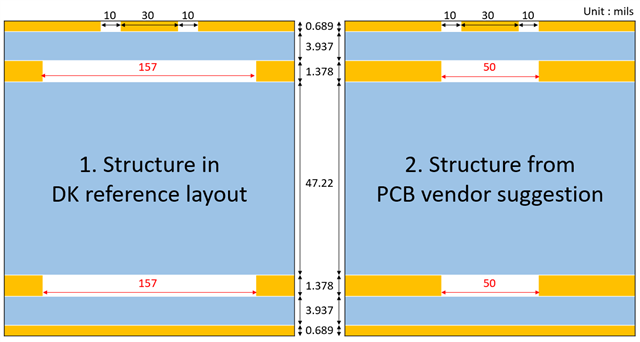
The left structure(no.1) is from the reference DK layout and the right structure (no.2) is suggested by out vendor.

I find your trace reference ground is layer4 ( bottom) and the inner layer (layer 2 & layer 3) empty area is quite larger than trace width (10+30+10 mils)

Could you share the reason why you do that and the advantage/disadvantage?

Parents Reply Children
  • Thank you for your kindness reply, but I still have some questions.

    1. why don't you choose layer3 for the reference ground ? (the dielectric thickness between layer 3 & 4  is only 3.9 mils)

    2. could you provide how to estimate the shrinking back range and distance?

  • So, you want the reference ground for the RF path to also be fully connected to the center pad ground. This is why we choose  the bottom layer, to have one layer with mostly ground being the reference ground, and to make a proper return path for noise. 

    We don't have an estimate on how this effects the performance, but what is important is the the output power and harmonics are measured on each specific design and that the radio matching components values are adjusted, so that you get desired output power and low harmonics on your design. 

    Best regards,
    Kaja

  • I think the layer 3 could meet the same condition for RF reference ground. What are your reasons to choose bottom layer, not layer 3?

    Does this design also help to filter the harmonic power? How does it work? (from your 2nd paragraph reply)

  • Webster Yang said:
    I think the layer 3 could meet the same condition for RF reference ground. What are your reasons to choose bottom layer, not layer 3?

    It was just a design choice done.. so you can use the third layer as well. 


    Webster Yang said:
    Does this design also help to filter the harmonic power? How does it work? (from your 2nd paragraph reply)
    Kaja said:
    We don't have an estimate on how this effects the performance, but what is important is the the output power and harmonics are measured on each specific design and that the radio matching components values are adjusted, so that you get desired output power and low harmonics on your design. 

    The radio matching network works as a filter as well as changing the impedance of the ANT pin on the nRF. So changing the values of these components are necessary to compensate for the difference from the reference design to the costume design. 

    Best regards,
    Kaja 

Related