
hi
Working with Linux operating system I faced the problem not knowing how can the nrf52840 device name be changed via the SPI protocol and what frame format should be used?
I would appreciate if you help me with step by step guidance.
Many thanks
hi
Working with Linux operating system I faced the problem not knowing how can the nrf52840 device name be changed via the SPI protocol and what frame format should be used?
I would appreciate if you help me with step by step guidance.
Many thanks
Hello,
I am not sure what you are asking. What name do you want to change? Is the nRF52840 connected to your linux computer using SPI?
Best regards,
Edvin
Hello
Yes nrf52840 connected to a core board with linux operation system using SPI . How can I merge advertise and SPI(master and slave) communications examples into one code so that the string that nrf receives as a slave will sit instead of the device name ?
#define DEVICE_NAME "Nordic"
On the other hand, the main issue is what should be the spi frame format for Linux?
nRF5_SDK_15.2.0_9412b96\examples\peripheral\spis
So your linux machine is running an SPI master? How did you connect the pins? What is the SPI speed that the SPI master is using?
Can you please test all the SPI modes, NRF_SPIS_MODE_0 to NRF_SPIS_MODE_3.
You can set it like this:
    nrf_drv_spis_config_t spis_config = NRF_DRV_SPIS_DEFAULT_CONFIG;
    spis_config.csn_pin               = APP_SPIS_CS_PIN;
    spis_config.miso_pin              = APP_SPIS_MISO_PIN;
    spis_config.mosi_pin              = APP_SPIS_MOSI_PIN;
    spis_config.sck_pin               = APP_SPIS_SCK_PIN;
    spis_config.mode                  = NRF_SPIS_MODE_0

    APP_ERROR_CHECK(nrf_drv_spis_init(&spis, &spis_config, spis_event_handler));
If that doesn't work, can you please try to capture a logic trace of the SPI wires?
Best regards,
Edvin
In the target application, Linux and NRF will behave as master and slave depending on the type of request, but to test the performance of a part of the application, currently Linux is used as Master and NRF as Slave.
When I change the pins defined in the example (spi&spis) to custom board pins, data is not sent/received.
I uploaded the samples (spi&spis) on two NRF DK boards by changing the pins I mentioned earlier, but still no data is being exchanged.
I also repeated this with the NRF DK board as a slave and the STM 32 as a master, but I could not send/receive data.
Master DK and Slave DK are connected by wire without any element between them
I don't know what is the SPI speed but I didn't change the speed in the SPI example.
spis_config.mode = NRF_SPIS_MODE added to SPIS example in main.c and tested 0-3 but the problem still persists.
If you take the unmodified spi&spis samples on two nRF DK boards (if you are not sure whether they are unmodified or not, download and unzip the SDK again).
Then let me know what pins you connected between the DKs. If possible, take a photo, and upload it here. Can you also show me the logs that you are seeing on both devices?
I have no problem with the default pins on the DK boards and data is sent / received correctly. The problem is when the pins numbers change to:
cs:P0.24(AD20)
CLK:P0.15(AD10)
mosi:P0.17(AD12)
miso:P0.22(AD18)
in sdk_config.h
Sorry, I am a beginner. I tried to send a photo on this page, but I failed to send it.
I can get "<info> app: Transfer completed. Received: ÿÿÿÿÿÿÿ " from slave and " <info> app: Transfer completed "from master with spi usb to uart by terminal .
Is this actually running on a custom board, or on the DK?
If it is on the DK, the reason it doesn't work is that the pins P0.17 and P0.22 are not routed out to the GPIO headers by default. If you look on the back of the DK, it shows you some of the pins and their use. e.g. pin P0.13-P0.16 are used for the LEDs (but they are routed out, so that is OK, as long as the application are not trying to control those GPIOs by toggling LEDs at the same time as you are trying to use them as SPI pins).
However, P0.17 and P0.22 are used as QSPI pins for the external flash chip on the DK, so these are not connected to the GPIO headers. You can see on the back of the DK what solder bridges you would have to cut and solder in order to do so. For these specifically, you would need to:
P0.17: cut SB17, solder SB23
P0.22: cut SB15, solder SB25
Alternatively, test with different GPIOs, if you want to do it on the DK.
Best regards,
Edvin
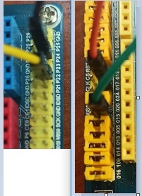
These examples were tested with changed pins on both the DK and the custom board and both have the same problem.
The photo below is taken of the SPI pins (cs:P0.24,CLK:P0.15,mosi:P0.17,miso:P0.22) on the DK :
That is not a Nordic nRF52840 DK.
So when testing on the DK, did you modify the solder bridges like described in my previous reply?
And do you connect MOSI -> MOSI and MISO -> MISO in your SPI connection? And CS/SS -> CS/SS and CLK -> CLK?
Hello Edvin
I succeeded to get the data from the slave on the custom board.
thanks for your reply.
Best regards,
Nasim
Hello Nasim,
I am glad to hear! If it is not too much of a problem, I am curious to know what the problem turned out to be. It would also help knowing these common pit falls, to be able to help other users quicker in the future.
Best regards,
Edvin

