nRF52832 Errata 58 SPIM Fix

Hi All,

Project Information:
nrf52832
nRF5 SDK 17.1.0

Segger 5.70a

We have a custom board design that is using the Analog Devices AD7785 AFE to interface with strain gauges. The AFE uses SPI to communicate. According to the datasheet and an FAE, the AFE requires single byte SPI transactions in order to communicate and use the chip. I eventually found out about the errata for the nrf52832 that involves the SPIM driver not being capable of doing transfers that have the receive length set to 1. I have seen the suggested fix from the errata page here: Nordic Semiconductor Infocenter involving setup_workaround_for_ftpan_58(), but I'm not sure how to implement it properly.

The discussion and response with code example in this post Problems Implementing Workaround to get nrf52 to send an octet / one byte through SPI - Nordic Q&A - Nordic DevZone - Nordic DevZone (nordicsemi.com) seems to only cover how to transmit a single byte using SPI, which I have been able to accomplish by setting the rx_length in nrf_drv_spi_transfer() to 0. But I am looking to learn how to use setup_workaround_for_ftpan_58() to receive one byte as that is necessary to read data from the AFE according to the FAE.

Parents
  • The datasheet clearly indicates multi-byte transfer is possible and indeed expected; see Fig 18 and Fig 19. Perhaps the FAE didn't gather what you were seeking. If using /CS repeated byte transfer is reliable. If not using /CS it might be wise to priodically use a reset sequence thus:

    "The serial interface can be reset by writing a series of 1s on the DIN input. If a Logic 1 is written to the AD7785 line for at least 32 serial clock cycles, the serial interface is reset"

    Always wise to ensure transfers are reliable by a periodic readback of registers to ensure 1) the registers are set correctly and 2) the SPI sync is intact in case not using /CS

  • Hi , thanks for the reply! I will contact the FAE again to confirm. I just took a look at the figures in the datasheet you mentioned, they appear to be referencing the collection of data from the AFE.

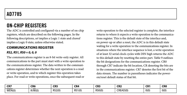
    The image below from page 14 of the datasheet is where the issue in question is arising from. In order to write to/read from the non data registers of the chip, it appears to require a single byte write to the comms register, and then require another CS toggle with 8 clocks to read from registers (i.e. status registers/identification registers). I originally tried using a multibyte transmission (1 transmit byte, 1 receive byte) but the AFE did not operate correctly doing so in this manner. That is when I contacted the FAE and was told that these specific communications required the individual SPI transmissions/receptions. 

  • Nope, multibyte transfer works. Try something like this (not tested) to read a number of registers (set CREAD to 1 if want to keep reading same register n times)

    Edit: Correction, consecutive register writes must prefix each register with the register address even in a block read/write (ie no auto-increment as in other similar parts). A multi-byte operation still works, however: <reg1><data><reg2><data>.. "For read or write operations, once the subsequent read or write operation to the selected register is complete, the interface returns to where it expects a write operation to the communications register"

    // ADC commands - check these, just did quick read of datasheet
    #define ADC_COMMAND_WR ( 0xC0 )  // write register command
    #define ADC_COMMAND_RR ( 0x00 )  // read register command
    
      uint8_t spiBuffer[5] = {0};
      // Read some registers (see datasheet for sizes) starting at (say) address 0
      spiBuffer[0] = ADC_COMMAND_RR + firstreg;  // command id + register 0 id then read 4 registers
      spiBuffer[1] = 0; // dummy tx value to read 8-bit reg 0
      spiBuffer[2] = ADC_COMMAND_RR + nextreg;
      spiBuffer[3] = 0; // dummy tx value to read 16-bit reg 2
      spiBuffer[4] = 0; // dummy tx value to read 16-bit reg 2
      // Send command and read the response
      spiTransact(sizeof(spiBuffer));

Reply
  • Nope, multibyte transfer works. Try something like this (not tested) to read a number of registers (set CREAD to 1 if want to keep reading same register n times)

    Edit: Correction, consecutive register writes must prefix each register with the register address even in a block read/write (ie no auto-increment as in other similar parts). A multi-byte operation still works, however: <reg1><data><reg2><data>.. "For read or write operations, once the subsequent read or write operation to the selected register is complete, the interface returns to where it expects a write operation to the communications register"

    // ADC commands - check these, just did quick read of datasheet
    #define ADC_COMMAND_WR ( 0xC0 )  // write register command
    #define ADC_COMMAND_RR ( 0x00 )  // read register command
    
      uint8_t spiBuffer[5] = {0};
      // Read some registers (see datasheet for sizes) starting at (say) address 0
      spiBuffer[0] = ADC_COMMAND_RR + firstreg;  // command id + register 0 id then read 4 registers
      spiBuffer[1] = 0; // dummy tx value to read 8-bit reg 0
      spiBuffer[2] = ADC_COMMAND_RR + nextreg;
      spiBuffer[3] = 0; // dummy tx value to read 16-bit reg 2
      spiBuffer[4] = 0; // dummy tx value to read 16-bit reg 2
      // Send command and read the response
      spiTransact(sizeof(spiBuffer));

Children
  • Okay thanks, I will look into this. The FAE I spoke to thinks you may be correct, but I will test and comment on the results when I get to it. 

  • After looking into this solution, it looks like the AFE can be communicated with using multi-byte transactions. There are 2 issues we are still running into. One is that the data being sent from the AFE to the micro is not consistent with what the datasheet says to expect. We are getting elevated within the manufacturer dev team for assistance on that. The other issue is that the nordic SPI driver appears to "miss" bits on the MISO pin. For instance, a logic analyzer shows MISO sends 0x8B (which is what the datasheet says to expect), but the nordic driver returns with a value of 0x83. This happens in many occasions, but I will make a separate post for this topic. Thanks for your help!

  • You may have already tried this, but if not it will improve reliability of reception. Increase the nRF52 drive strength to CS, SCK and MOSI output drivers to H0H1 instead of the default S0S1. This can be done after the SPI init nrfx_spim_init() if you are using Nordic libraries and want to avoid editing those.

    H0H1 on the clock pin SCK in particular can avoid incorrect data reception on MISO and only a very high bandwidth 'scope will show the jitter on the AFE clock in pin transition which can cause bit corruption.

Related