nRF5340 Internal RC Oscillator Question for DTM USB Configuration

Hi,

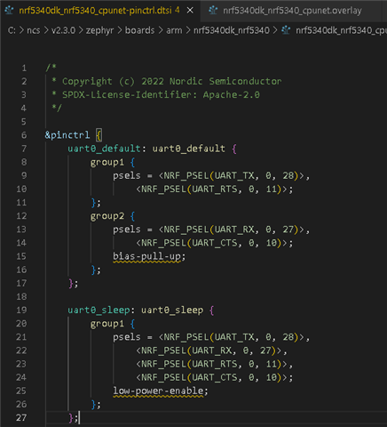
I used both SDK v2.3.0 and v2.4.0, I was able to get DTM example working over USB CDC ACM with nrf5340 DK PCA10095. I switched to my custom board which has no 32KHz XTAL between P0.00/XL1-P0.01/XL2. I changed both direct_test_mode\prj.conf and direct_test_mode\child_image\remote_shell\prj.conf to use internal RC oscillator to include:

CONFIG_CLOCK_CONTROL_NRF_K32SRC_RC=y
CONFIG_CLOCK_CONTROL_NRF_K32SRC_500PPM=y
CONFIG_CLOCK_CONTROL_NRF_K32SRC_SYNTH=y

My issue is right after I programmed the combined application and network image (merged_domains.hex) with nRF Connect Programmer, I was able to see the USB VCOM (when nRF Connect Programmer trace has "10:34:02.245 Getting serialport options from persistent store D0C417815ECA4DEC.pc-nrfconnect-programmer") for 7 seconds then disappeared.

I browsed on DevZone and saw a few questions about internal RC oscillator but I am not sure what is the root cause in my case. Please advise.

Regards

Parents
  • Hello,

    For boards that don't include the 32K XTAL, we generally recommend selecting the LFRC source. It is not as accurate as LFSYNTH, but it gives you lower sleep currents since it does not rely on the HFCLK. You can use our online power profiler to compare the difference between LRFC and LFXO in terms of power consumption.

    CONFIG_CLOCK_CONTROL_NRF_K32SRC_RC=y
    CONFIG_CLOCK_CONTROL_NRF_K32SRC_500PPM=y
    CONFIG_CLOCK_CONTROL_NRF_K32SRC_SYNTH=y

    Here you are selecting both LFRC and LFXO, but it is only possible to select one. It is also important that you select the same clock source for all images in your project.

    It should be sufficient to apply CONFIG_CLOCK_CONTROL_NRF_K32SRC_RC=y for each build

    Best regards,

    Vidar

  • Hi Vidar,

    Thank you for the suggestion. With just CONFIG_CLOCK_CONTROL_NRF_K32SRC_RC=y alone, I am not able to see USB VCOM port from Windows device manager at all. With just CONFIG_CLOCK_CONTROL_NRF_K32SRC_SYNTH=y alone, Windows shows USB VCOM for about 7 seconds as before. I attach direct_test_mode/prj.conf here:

    # Configure assertions
    CONFIG_ASSERT=y
    CONFIG_ASSERT_NO_COND_INFO=y
    CONFIG_ASSERT_NO_MSG_INFO=y
    
    CONFIG_HW_STACK_PROTECTION=y
    
    CONFIG_CONSOLE=n
    CONFIG_UART_CONSOLE=n
    
    CONFIG_LOG=y
    CONFIG_LOG_PRINTK=y
    CONFIG_USE_SEGGER_RTT=y
    CONFIG_LOG_BACKEND_RTT=y
    
    # Use necessary peripherals
    CONFIG_NRFX_TIMER0=y
    CONFIG_NRFX_TIMER1=y
    CONFIG_NRFX_TIMER2=y
    
    CONFIG_FEM_AL_LIB=y
    
    CONFIG_CLOCK_CONTROL=y
    CONFIG_CLOCK_CONTROL_NRF=y
    CONFIG_CLOCK_CONTROL_NRF_K32SRC_SYNTH=y
    

  • Hi Vidar, your loads work on my custom board. This is great. The EE on my custom board said we have the inductors. I will look into on how to disable DCDC. Please share the CONFIG to disable DCDC. Thank you so much for your helps. 

  • Hi,

    That is great. I didn't really suspect the inductors to be the problem; I just disabled the DCDC regulators for good measure. It could be that the inductor(s) are mounted, but one is missing or has the wrong value. Typically, if you don't have any inductors mounted but enable the DCDC, the device will become "bricked" as the unstable supply will prevent you from re-programming it.

    Relevant Kconfig symbols for the DCDC regulator are:

    CONFIG_BOARD_ENABLE_DCDC_APP, BOARD_ENABLE_DCDC_HV, and CONFIG_BOARD_ENABLE_DCDC_NET. 

    Ref. https://github.com/nrfconnect/sdk-zephyr/blob/main/boards/arm/nrf5340dk_nrf5340/Kconfig#L8 

  • Hi Vidar,

    I removed the 32kHz on nRF5340 DK PCA10095. Without disabling DCDC regulators, I was able to see the same problem (USB VCOM disappeared after a few seconds) as on my custom PCBA.

    I then added:

    CONFIG_BOARD_ENABLE_DCDC_APP=n
    CONFIG_BOARD_ENABLE_DCDC_HV=n
    CONFIG_BOARD_ENABLE_DCDC_NET=n

    to both direct_test_mode/prj.conf and \direct_test_mode\child_image\remote_shell\prj.conf. The problem still exist. Please let me know how you did disabling DCDC regulators exactly.

    Thanks,

    Dennis

  • Hi Dennis,

    gfgf2400a said:
    CONFIG_BOARD_ENABLE_DCDC_APP=n
    CONFIG_BOARD_ENABLE_DCDC_HV=n
    CONFIG_BOARD_ENABLE_DCDC_NET=n

    It's sufficient to apply these configurations to the FW image(s) running on the app core since the regulators are controlled from the application domain. Applying the same settings for a netcore image won't have any effect.

    I disabled the DCDC regulators by adding the configurations above to the \direct_test_mode\child_image\remote_shell\prj.conf file. 


    Best regards,

    Vidar

  • Hi Vidar,

    I'm trying to use SDK v.2.3.0 nrf/samples/bluetooth/direct_test_mode with built-in USB on nRF5340 or the UART-to-USB virtual COM port with an FTDI cable that has a TC2030 connector on the end, but that hasn't worked.

    The TC2030 connector looks like this on our PCB:

     TC2030-MCP-NL.pdf

    Based on this document DTM for DUT

    Our UART_DBG_TX pin is P0.28 and the UART_DBG_RX pin is P0.27. Do I need to edit the nrf5340dk_nrf5340_cpunet-pinctrl.dtsi file like so?

    And do I add CONFIG_DTM_USB=y to my prj.conf file without adding any files like zephyr/drivers/usbc.h or other code to use DTM on my custom board via USB? I also added CONFIG_CLOCK_CONTROL_NRF_K32SRC_RC=y to the prj.conf file since we don't have an external 32KHz oscillator between X1 and X2. Is there anything else I need to do to make the nRF Connect DTM app on my Windows 10 PC work with my custom board?

    The reason I ask is because the attached DK hex files you provided didn't automatically work with my custom board.

Reply
  • Hi Vidar,

    I'm trying to use SDK v.2.3.0 nrf/samples/bluetooth/direct_test_mode with built-in USB on nRF5340 or the UART-to-USB virtual COM port with an FTDI cable that has a TC2030 connector on the end, but that hasn't worked.

    The TC2030 connector looks like this on our PCB:

     TC2030-MCP-NL.pdf

    Based on this document DTM for DUT

    Our UART_DBG_TX pin is P0.28 and the UART_DBG_RX pin is P0.27. Do I need to edit the nrf5340dk_nrf5340_cpunet-pinctrl.dtsi file like so?

    And do I add CONFIG_DTM_USB=y to my prj.conf file without adding any files like zephyr/drivers/usbc.h or other code to use DTM on my custom board via USB? I also added CONFIG_CLOCK_CONTROL_NRF_K32SRC_RC=y to the prj.conf file since we don't have an external 32KHz oscillator between X1 and X2. Is there anything else I need to do to make the nRF Connect DTM app on my Windows 10 PC work with my custom board?

    The reason I ask is because the attached DK hex files you provided didn't automatically work with my custom board.

Children
  • Hi,

    It is important that you apply the CONFIG_CLOCK_CONTROL_NRF_K32SRC_RC=y setting to both the DTM sample running on the network core and the remote_shell running on the app core. You can do this by adding 'CONFIG_CLOCK_CONTROL_NRF_K32SRC_RC=y' to prj.conf and the child_image/remote_shell/prj.conf file. 

    rockerderek said:
    Our UART_DBG_TX pin is P0.28 and the UART_DBG_RX pin is P0.27. Do I need to edit the nrf5340dk_nrf5340_cpunet-pinctrl.dtsi file like so?

    Yes, this should work. However, the recommended approach is to create a board overlay in your project directory. This way you won't have to edit the original board files. There is already an overlay present overlay for the remote_shell application in the project directory here /direct_test_mode/child_image/remote_shell/boards/nrf5340dk_nrf5340_cpuapp.overlay which you can use.

    overriding UART pin assigments for app core:

    diff --git a/child_image/remote_shell/boards/nrf5340dk_nrf5340_cpuapp.overlay b/child_image/remote_shell/boards/nrf5340dk_nrf5340_cpuapp.overlay
    index 3bdcc7c..2ca2cc9 100644
    --- a/child_image/remote_shell/boards/nrf5340dk_nrf5340_cpuapp.overlay
    +++ b/child_image/remote_shell/boards/nrf5340dk_nrf5340_cpuapp.overlay
    @@ -24,3 +24,13 @@
     		<&gpio0 7 0>;
     	};
     };
    +
    +&pinctrl {
    +	uart0_default {
    +		group1 {
    +			psels = < NRF_PSEL(UART_TX, 0, 28) >,
    +				<NRF_PSEL(UART_RTS, 0, 11) >;
    +		};
    +	};
    +};
    +

  • Hi Vidar,

    I followed your steps and added those things to the overlay file and other prj.conf file, but it still shows "can not communicate with device. 

    Brad

Related