
Dear,
Please, could help me ?
My knowledge in RF is basic.
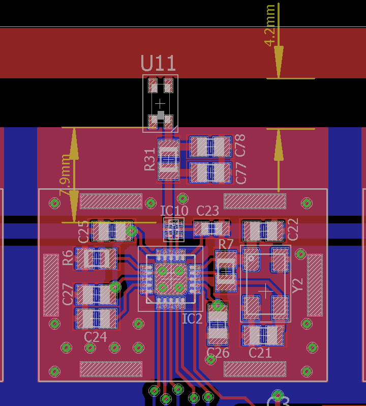
I am developing a system to use 8 RF channels (nRF24L01 +) simultaneously. I'm using Balum 2450BM14A0002 and antenna 2450AT18D0100 ( both Johanson). The board layout was as seen in the figure.
I attached the circuit containing all 8 channels.
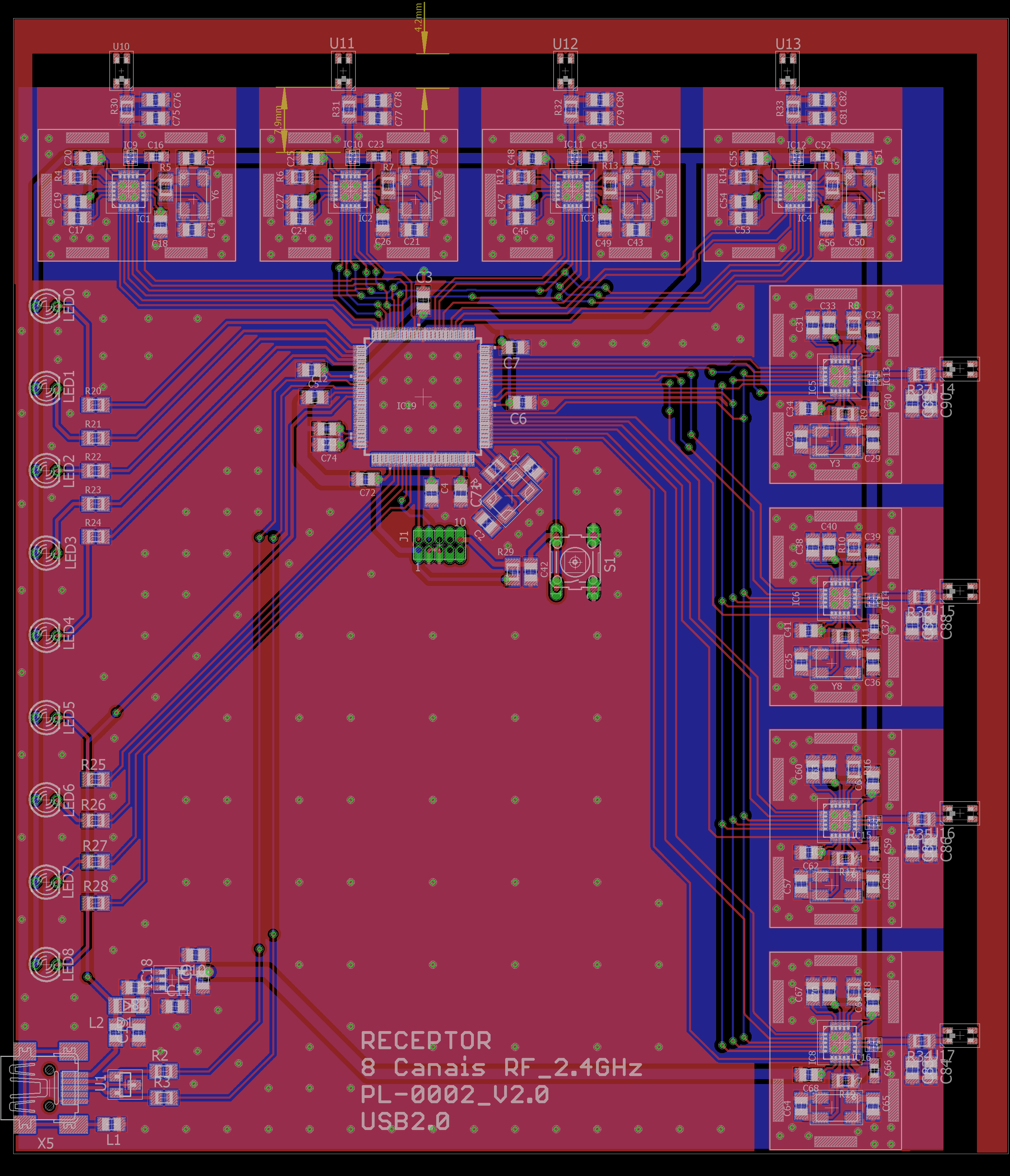
My question is: This is a good layout or need to modify the layout? Any modification is necessary?
The two capacitors and the resistor close to the antenna is to improve tunning, but I dont know how calcule the capacitor and resistor value. It was recomended to me for a friend. This is a precaution.
This layout will work correctly? Or do I have problems with the signal? I'm considering creating a drilled area under the antenna.
I appreciate all the help. Thank you
Alexandre
