nrf52832 I2C lines fail to work on pins 20 (SDA) and 21 (SCK)

Using NCS v2.3.0

Boards:

nrf52dk-nrf52832

Custom board with 317030213 BLE module (uses nrf52832)

I wrote code to use I2C to interface with a GPIO Expander (MCP23008). Working with the dev-kit and picking I2C pins i got nice looking results for both SCK and SDA. During routing of our custom board, we selected pins that made for easiest routing since every GPIO pin can be connected to any peripheral. I spent alot of time debugging my custom board that uses pins p0.20 for SDA and pins p0.21 for SCK wondering why it didnt work.

I went back to my dev board and confirmed that using pins p0.20 and p0.21 prevents proper waveforms from being output. By simply switching the pin assignements to p0.24/25 and changing nothing else in my code, the I2C communications work perfectly. Is there anything i may be missing that is specific to these pins that would prevent I2C from working properly? I cant change the pins on my custom board as they have already been fabricated. i2c_write_dt() returns ernno -5

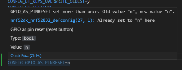
NOTE: I am aware that p0.21 is used as the reset button on the dev kit. I have set CONFIG_GPIO_AS_PINRESET=n in an attempt to fix this issue but this did not fix the issue.

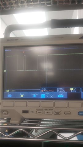
SCREENSHOTS OF I2C OUTPUT WITH PIN ASSIGNMENTS

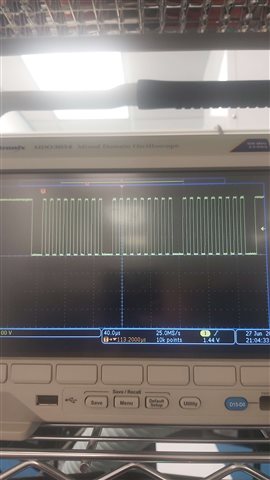
SCK and SDA for pins 24 and 25

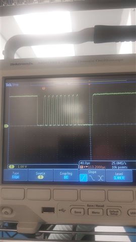
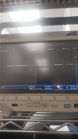
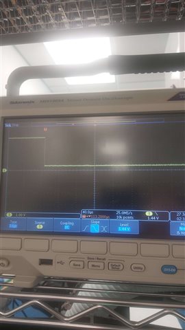
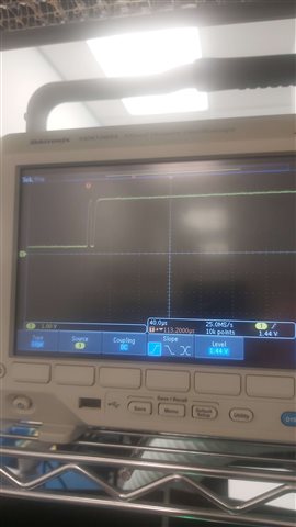
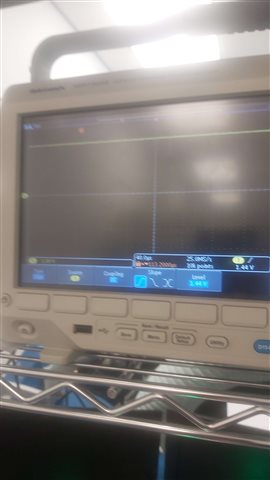
SDA (two images - long delay) and SCK (no output) for pins 20 and 21
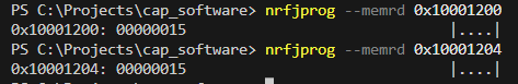
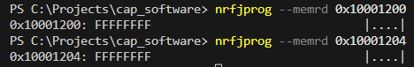
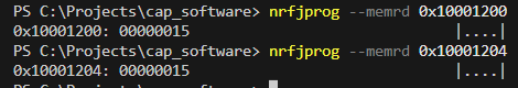
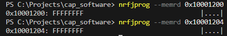
INFO DUMP

i2c code

#define I2C0_NODE DT_NODELABEL(mysensor)
static const struct i2c_dt_spec i2c_gpio_expander = I2C_DT_SPEC_GET(I2C0_NODE);
//GLOBALS
volatile uint8_t limit_switch_values = 0;
static const struct i2c_dt_spec i2c_gpio_expander = I2C_DT_SPEC_GET(I2C0_NODE);
static const struct gpio_dt_spec gpio_expander_interrupt = GPIO_DT_SPEC_GET_OR(DT_ALIAS(gpioint), gpios, {0});
static struct gpio_callback gpio_expander_cb;
/////////

//PROTOTYPES
void gpio_expander_irq(const struct device *dev, struct gpio_callback *cb, uint32_t pins);
void gpio_expander_get_states(struct k_work *work);
K_WORK_DEFINE(get_states, gpio_expander_get_states);
////////////
void gpio_expander_irq(const struct device *dev, struct gpio_callback *cb, uint32_t pins)
{
    k_work_submit(&get_states);

    return;
}

void gpio_expander_get_states(struct k_work *work)
{
    uint8_t data;
    int ret;

    printk("[%s] Limit State Changed\n", __TITLE__);
    uint8_t config[2] = {0xF0, 0xC3};

    ret = i2c_write_dt(&i2c_gpio_expander, config, sizeof(config));
    if(ret != 0){
        printk("[%s] Failed to read from I2C device. Errno %d\n", __TITLE__, ret);
        return;
    }
    //save new limit switch values
    limit_switch_values = data;

    return;
}

prj.conf

# enable console
CONFIG_CONSOLE=y
CONFIG_UART_CONSOLE=n

#LOGGING SELECTIONS##################
#Setup logging, set all values to n to disable all logging output
CONFIG_LOG=y
CONFIG_LOG_PRINTK=y

#setup rtt output for printk() statements
#necessary as nrf52832 only has 1 uart which will be used for the pi
CONFIG_STDOUT_CONSOLE=n #this should be n
CONFIG_USE_SEGGER_RTT=y
CONFIG_RTT_CONSOLE=y
CONFIG_PRINTK=y
CONFIG_BT_DEBUG_LOG=y
CONFIG_LED_STRIP_LOG_LEVEL_DBG=y
###################################

#enable uart for pi communication
CONFIG_SERIAL=y
CONFIG_UART_ASYNC_API=y

#enable pwm for DC motor and solenoid control
CONFIG_PWM=y

#enable GPIO for basic GPIO setups
CONFIG_GPIO=y

#enable I2C for GPIO expander
CONFIG_I2C=y

#setup for LED strip
CONFIG_SPI=y
CONFIG_LED_STRIP=y
CONFIG_WS2812_STRIP=y
CONFIG_SOC_NRF52832_ALLOW_SPIM_DESPITE_PAN_58=y

#enable ADC for VM and 5V readings
CONFIG_ADC=y

#enable specific timers
CONFIG_COUNTER=y
CONFIG_COUNTER_TIMER0=y
CONFIG_COUNTER_TIMER1=y

#BLUETOOTH SETTINGS
# Increased stack due to settings API usage
CONFIG_SYSTEM_WORKQUEUE_STACK_SIZE=2048

CONFIG_BT=y
CONFIG_BT_SMP=y
CONFIG_BT_SIGNING=y
CONFIG_BT_PERIPHERAL=y
CONFIG_BT_DIS=y
CONFIG_BT_ATT_PREPARE_COUNT=5
CONFIG_BT_BAS=y
CONFIG_BT_PRIVACY=y
CONFIG_BT_DEVICE_APPEARANCE=833
CONFIG_BT_DEVICE_NAME_DYNAMIC=y
CONFIG_BT_DEVICE_NAME_MAX=65

CONFIG_BT_KEYS_OVERWRITE_OLDEST=y
CONFIG_BT_SETTINGS=y
CONFIG_FLASH=y
CONFIG_FLASH_PAGE_LAYOUT=y
CONFIG_MPU_ALLOW_FLASH_WRITE=y
CONFIG_NVS=y
CONFIG_SETTINGS=y

CONFIG_HEAP_MEM_POOL_SIZE=4096
dts

/ {
    model = " ";
    compatible = " ";

    chosen {
        zephyr,console = &uart0;
        zephyr,shell-uart = &uart0;
        zephyr,uart-mcumgr = &uart0;
        zephyr,bt-mon-uart = &uart0;
        zephyr,bt-c2h-uart = &uart0;
        zephyr,sram = &sram0;
        zephyr,flash = &flash0;
        zephyr,code-partition = &slot0_partition;
    };

    gpiocustom {
        compatible = "gpio-keys";

        stepperdir:stepper_dir {
            gpios = <&gpio0 (STEPPER_DIR_PIN) GPIO_ACTIVE_HIGH>;
            label = "Stepper Motor Direction";
        };

        stepperen:stepper_en {
            gpios = <&gpio0 (STEPPER_EN_PIN) GPIO_ACTIVE_HIGH>;
            label = "Stepper Enable";
        };

        stepperstep:stepper_step {
            gpios = <&gpio0 (STEPPER_STEP_PIN) GPIO_ACTIVE_HIGH>;
            label = "Stepper Step Control";
        };

        pi_power_en:pi_power_en {
            gpios = <&gpio0 (RPI_EN_PIN) GPIO_ACTIVE_HIGH>;
            label = "PI Power Enable";
        };

        motorencoderL:motorencoderL {
            gpios = <&gpio0 (ENCODER_L_PIN) GPIO_PULL_DOWN>;
            label = "Left DC Motor Encoder Input";
        };
       
        motorencoderR:motorencoderR {
            gpios = <&gpio0 (ENCODER_R_PIN) GPIO_PULL_DOWN>;
            label = "Right DC Motor Encoder Input";
        };

        gpioexpanderinterrupt:gpioexpanderinterrupt {
            gpios = <&gpio0 (GPIO_INT_PIN) GPIO_PULL_DOWN>;
            label = "GPIO Expander Interrupt";
        };
    };

    pwmcustom {
        compatible = "pwm-leds";

        pwm_dc0: pwm_dc_0 {
            pwms = <&pwm0 0 PWM_MSEC(20) PWM_POLARITY_NORMAL>;
        };

        pwm_dc1: pwm_dc_1 {
            pwms = <&pwm0 1 PWM_MSEC(20) PWM_POLARITY_NORMAL>;
        };

        pwm_sol0: pwm_sol_0 {
            pwms = <&pwm1 0 PWM_MSEC(20) PWM_POLARITY_NORMAL>;
        };

        pwm_sol1: pwm_sol_1 {
            pwms = <&pwm1 1 PWM_MSEC(20) PWM_POLARITY_NORMAL>;
        };

        pwm_sol2: pwm_sol_2 {
            pwms = <&pwm1 2 PWM_MSEC(20) PWM_POLARITY_NORMAL>;
        };
    };

    leds {
        compatible = "gpio-leds";
       
        led_en: led_en {
            gpios = <&gpio0 (LED_EN_PIN) GPIO_ACTIVE_HIGH>;
            label = "5V0 Power LED";
        };

        led_red: led_red {
            gpios = <&gpio0 (LED_R_EN_PIN) GPIO_ACTIVE_HIGH>;
            label = "Red Button LED";
        };

        led_green: led_green {
            gpios = <&gpio0 (LED_G_EN_PIN) GPIO_ACTIVE_HIGH>;
            label = "Green Button LED";
        };

        led_yellow: led_yellow {
            gpios = <&gpio0 (LED_Y_EN_PIN) GPIO_ACTIVE_HIGH>;
            label = "Yellow Button LED";
        };


    };

    buttons {
        compatible = "gpio-keys";
        button0: button_0 {
            gpios = <&gpio0 (BUTTON_1_PIN) (GPIO_PULL_UP | GPIO_ACTIVE_LOW)>;
            label = "Push button switch 0";
        };
        button1: button_1 {
            gpios = <&gpio0 (BUTTON_2_PIN) (GPIO_PULL_UP | GPIO_ACTIVE_LOW)>;
            label = "Push button switch 1";
        };
        button2: button_2 {
            gpios = <&gpio0 (BUTTON_3_PIN) (GPIO_PULL_UP | GPIO_ACTIVE_LOW)>;
            label = "Push button switch 2";
        };
    };
   
    /* These aliases are provided for compatibility with samples */
    aliases {
        pwm-dc0 = &pwm_dc0;
        pwm-dc1 = &pwm_dc1;
        pwm-sol0 = &pwm_sol0;
        pwm-sol1 = &pwm_sol1;
        pwm-sol2 = &pwm_sol2;
        sw0 = &button0;
        sw1 = &button1;
        sw2 = &button2;
        encoderleft = &motorencoderL;
        encoderright = &motorencoderR;
        gpioint = &gpioexpanderinterrupt;
    };
};

&adc {
    status="okay";

    #address-cells = <1>;
    #size-cells = <0>;
 
    channel@2 {
        reg = <2>;
        zephyr,gain = "ADC_GAIN_1";
        zephyr,reference = "ADC_REF_INTERNAL";
        zephyr,acquisition-time = <ADC_ACQ_TIME_DEFAULT>;
        zephyr,resolution = < 12 >;
        zephyr,input-positive = <NRF_SAADC_AIN2>;
    };
 
    channel@3 {
        reg = <3>;
        zephyr,gain = "ADC_GAIN_1";
        zephyr,reference = "ADC_REF_INTERNAL";
        zephyr,acquisition-time = <ADC_ACQ_TIME_DEFAULT>;
        zephyr,resolution = < 12 >;
        zephyr,input-positive = <NRF_SAADC_AIN3>;
    };
 };

&gpiote {
    status = "okay";
};

&gpio0 {
    status = "okay";
};

&uart0 {
    status = "okay";
    compatible = "nordic,nrf-uarte";
    current-speed = <115200>;
    pinctrl-0 = <&uart0_default>;
    pinctrl-1 = <&uart0_sleep>;
    pinctrl-names = "default", "sleep";
};

&i2c1 {
    compatible = "nordic,nrf-twim";
    status = "okay";
    pinctrl-0 = <&i2c1_default>;
    pinctrl-1 = <&i2c1_sleep>;
    pinctrl-names = "default", "sleep";
};

&pwm0 {
    status = "okay";
    pinctrl-0 = <&pwm0_default>;
    pinctrl-1 = <&pwm0_sleep>;
    pinctrl-names = "default", "sleep";
};

&pwm1 {
    status = "okay";
    pinctrl-0 = <&pwm1_default>;
    pinctrl-1 = <&pwm1_sleep>;
    pinctrl-names = "default", "sleep";
};

&spi2 {
    compatible = "nordic,nrf-spim";
    status = "okay";
    pinctrl-0 = <&spi2_default>;
    pinctrl-1 = <&spi2_sleep>;
    pinctrl-names = "default", "sleep";
};

&flash0 {

    partitions {
        compatible = "fixed-partitions";
        #address-cells = <1>;
        #size-cells = <1>;

        boot_partition: partition@0 {
            label = "mcuboot";
            reg = <0x00000000 0xc000>;
        };
        slot0_partition: partition@c000 {
            label = "image-0";
            reg = <0x0000C000 0x32000>;
        };
        slot1_partition: partition@3e000 {
            label = "image-1";
            reg = <0x0003E000 0x32000>;
        };
        scratch_partition: partition@70000 {
            label = "image-scratch";
            reg = <0x00070000 0xa000>;
        };
        storage_partition: partition@7a000 {
            label = "drill_storage";
            reg = <0x0007a000 0x00006000>;
        };
    };
};
overlay
&spi2{
    compatible = "nordic,nrf-spim";
    led_strip: ws2812@0 {
        compatible = "worldsemi,ws2812-spi";

        /* SPI */
        reg = <0>; /* ignored, but necessary for SPI bindings */
        spi-max-frequency = <SPI_FREQ>;

        /* WS2812 */
        chain-length = <16>; /* arbitrary; change at will */
        color-mapping = <LED_COLOR_ID_GREEN
                 LED_COLOR_ID_RED
                 LED_COLOR_ID_BLUE>;
        spi-one-frame = <ONE_FRAME>;
        spi-zero-frame = <ZERO_FRAME>;
    };
};

/ {
    aliases {
        led-strip = &led_strip;
    };
};

&i2c1 {
    mysensor: MCP23008@20 {
        compatible = "i2c-device";
        reg = < 0x20 >;
        label = "GPIO Expander";
    };
};
Parents
  • Hi there,

    Could you just double check that the GPIO peripheral indeed have access to the P0.21 and that it isn't allocated to the RESET circuitry? You can do that by reading out the PSELRESET[n] registers after flashing your application, you can use nRF Command Line Tools to read it out, like this:

    nrfjprog --memrd 0x10001200
    
    
    nrfjprog --memrd 0x10001204

    Also, have you tried to just change P0.21 to something else and see if it works?

    regards

    Jared

Reply
  • Hi there,

    Could you just double check that the GPIO peripheral indeed have access to the P0.21 and that it isn't allocated to the RESET circuitry? You can do that by reading out the PSELRESET[n] registers after flashing your application, you can use nRF Command Line Tools to read it out, like this:

    nrfjprog --memrd 0x10001200
    
    
    nrfjprog --memrd 0x10001204

    Also, have you tried to just change P0.21 to something else and see if it works?

    regards

    Jared

Children
  • Solved the issue! Your tests pointed me in the right direction; The issue was in vscode and was solved by adding "softreset" : true to the flash settings. Below are the steps i performed while working to a solution.

    Here is the output running the lines you suggested. It appears pin 21 is still allocated as the reset pin so this is likely the issue (not i2c stuff)

    I used nrf Connect for Desktop Programmer and erased the whole board. PSELRESET registers reset properly.

    I placed an extra line of CONFIG_GPIO_AS_PINRESET=n in my proj.conf (just to ensure that it is set to "n" in the build)

    Ran a pristine build, flashed my board and then re-ran the PSELRESET memory read. Still being allocated as reset pin


    I was able to find another ticket now that i knew it was specifically a reset pin issue. Ticket =  https://devzone.nordicsemi.com/f/nordic-q-a/100486/reset-pin-as-gpio   Glen M suggested to visit  https://nrfconnect.github.io/vscode-nrf-connect/guides/build_bind_tasks.html and add "softreset" : true to the settings.json file (I set it in the workspace.json as well).

    PSELRESET registers AFTER building and flashing board. Reset button no longer reseting code on devkit (good).

    I2C now working on P20 and P21. I can find the GPIO expander on the bus and it is responding to messages.

  • Hi,

    I'm happy to hear that you were able to resolve the case and returned with the solution, it'll make it easier for others that struggle with the same issue,

    regards

    Jared 

Related