

I've got a SPI slave device connected to my Laird BL652 (based on the nRF52832). The slave requires the following transaction on the SPI bus:
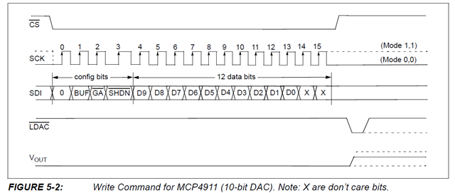
Note that the total transaction size is 16 bits.
The SPI section of the module's dts file looks like this:
&spi0 {
	compatible = "nordic,nrf-spi";
	/* Cannot be used together with i2c0. */
	/* status = "okay"; */
	cs-gpios = <&gpio0 22 GPIO_ACTIVE_LOW>;
	pinctrl-0 = <&spi0_default>;
	pinctrl-1 = <&spi0_sleep>;
	pinctrl-names = "default", "sleep";
};
And I've added an overlay that looks like this in order to enable the device and generate the CS signal on GPIO 18.
&spi0 {
    cs-gpios = <&gpio0 18 GPIO_ACTIVE_LOW>;
    status = "okay";
};
My test code to use the SPI looks like this:
    const struct spi_dt_spec spi_spec = {
        .bus = DEVICE_DT_GET(DT_NODELABEL(spi0))
    };
    if( spi_spec.bus == NULL ) {
        printk("SPI not initialized.\n");
        return SPI_NOT_INITIALIZED;
    } else if( ! device_is_ready(spi_spec.bus) ) {
        printk("SPI not ready.\n");
        return SPI_NOT_READY;
    }
    uint8_t spi_bytes[2] = {0};
    const struct spi_buf my_spi_buf[1] = {// Buffer to hold one set of SPI data
        [0].buf = spi_bytes,// The byte array to send
        [0].len = 2// Number of bytes in buffer
    };
    const struct spi_buf_set tx_buff = {
        .buffers = my_spi_buf,
        .count = 1
    };
    int spi_write_return = spi_write_dt(&spi_spec,&tx_buff);
    if( spi_write_return >= 0 ) {
        return MESSAGE_OK;
    } else {
        printk("Error number %d in SPI write.\n" , spi_write_return );
        return SPI_WRITE_ERROR;
    }
When I run the code, I get the following error message: <err> spi_nrfx_spi: configure: Word sizes other than 8 bits are not supported
The error number returned by spi_write_dt is -22.
Now, I'm not setting anything in the "operation" field of the spi_spec structure and I guess I need to. Here's the code from spi.h that describes all the various bit fields in the int16_t operation word.
/**
 * @brief SPI controller configuration structure
 *
 * @param frequency is the bus frequency in Hertz
 * @param operation is a bit field with the following parts:
 *
 *     operational mode    [ 0 ]       - master or slave.
 *     mode                [ 1 : 3 ]   - Polarity, phase and loop mode.
 *     transfer            [ 4 ]       - LSB or MSB first.
 *     word_size           [ 5 : 10 ]  - Size of a data frame in bits.
 *     duplex              [ 11 ]      - full/half duplex.
 *     cs_hold             [ 12 ]      - Hold on the CS line if possible.
 *     lock_on             [ 13 ]      - Keep resource locked for the caller.
 *     cs_active_high      [ 14 ]      - Active high CS logic.
 *     format              [ 15 ]      - Motorola or TI frame format (optional).
 * if @kconfig{CONFIG_SPI_EXTENDED_MODES} is defined:
 *     lines               [ 16 : 17 ] - MISO lines: Single/Dual/Quad/Octal.
 *     reserved            [ 18 : 31 ] - reserved for future use.
 * @param slave is the slave number from 0 to host controller slave limit.
 * @param cs is a valid pointer on a struct spi_cs_control is CS line is
 *    emulated through a gpio line, or NULL otherwise.
 * @warning Most drivers use pointer comparison to determine whether a
 * passed configuration is different from one used in a previous
 * transaction.  Changes to fields in the structure may not be
 * detected.
 */
struct spi_config {
	uint32_t		frequency;
#if defined(CONFIG_SPI_EXTENDED_MODES)
	uint32_t		operation;
	uint16_t		slave;
	uint16_t		_unused;
#else
	uint16_t		operation;
	uint16_t		slave;
#endif /* CONFIG_SPI_EXTENDED_MODES */

	const struct spi_cs_control *cs;
};
I would have hoped many of operation bits are set by default but I guess not. So I have the following questions:
- Given the SPI transaction as I showed it at the top of this question, what should be the values of the various operation bits.
- Is there a C bit-field data structure (as I created in the code fragment below) to make it easier to manage the fields?
As an experiment, I created the following code to set the bit fields in the operation word. I'm not sure I got them all correct but it's a start. I'm also setting the frequency to 1MHz.
    union op_combo {
        struct {
            uint16_t op_mode: 1;        // [0] - master or slave.
            uint16_t mode: 3;           // [ 1 : 3 ]   - Polarity, phase and loop mode.
            uint16_t transfer: 1;       // [ 4 ]       - LSB or MSB first.
            uint16_t word_size: 6;      // [ 5 : 10 ]  - Size of a data frame in bits.
            uint16_t duplex: 1;         // [ 11 ]      - full/half duplex.
            uint16_t cs_hold: 1;        // [ 12 ]      - Hold on the CS line if possible.
            uint16_t lock_on: 1;        // [ 13 ]      - Keep resource locked for the caller.
            uint16_t cs_active_high: 1; // [ 14 ]      - Active high CS logic.
            uint16_t format: 1;         // [ 15 ]      - Motorola or TI frame format (optional).
        } fields;
        uint16_t word;
    };

    const union op_combo operation = {
        .fields.op_mode = 0,
        .fields.mode = 0,
        .fields.transfer = 0,
        .fields.word_size = 8,
        .fields.duplex = 0,
        .fields.cs_hold = 0,
        .fields.lock_on = 0,
        .fields.cs_active_high = 0,
        .fields.format = 1
    };

    printk("op = 0x%x\n",operation.word);


    const struct spi_dt_spec spi_spec = {
        .bus = DEVICE_DT_GET(DT_NODELABEL(spi0)),
        .config.operation = operation.word,
        .config.frequency = 1000000,
        .config.slave = 0
    };
Now I'm getting the following runtime error: <err> spi_nrfx_spi: spi_context_wait_for_completion: Timeout waiting for transfer complete
And error code -116 returned from spi_write_dt.
Note that I'm not seeing anything coming out of the SPI bus so I'm guessing the timeout is set to 0 somewhere and the driver is timing out immediately.
From what I understand, the driver is supposed to calculate the timeout based on the transfer size and clock rate, but there appear to be some bugs associated with this, namely bugs #53957 and #53965.
- I'm using toolchain version 2.3.0. Are these bugs fixed in that version? If not, is there a patch I can apply?
Thanks,
Bret

