AoA IQ samples analysis

Hi, 

I have run up the connectionless rx aoa sample based on NCS2.1.2. and get the cte IQ samples. just as below:

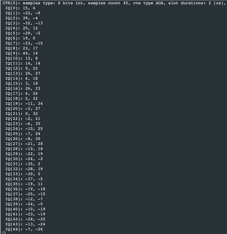
as the white paper's guidance. the pre-8samples is reference samples. and from the index of 8, IQ sampled each 4us.  totally 160us  for 45samples.  it's seems to normally runed.

but as my understanding about the samples above, from the index of 8. the IQ sampled according antten's switchpattern. and loop from switchpattern[2] to swichpattern[9]. there are 10 antennas and petterns I used.

that means

IQ[8]----switchpettern[2]

IQ[9]----switchpettern[3]

IQ[10]----switchpettern[4]

.......

IQ[15]----switchpettern[9]

IQ[16]----switchpettern[2]

IQ[17]----switchpettern[3]

.......

IQ[23]----switchpettern[9]

........


thus,  the phase diff between(IQ[8] and IQ[9]) should equal with (IQ[16] and IQ[17]).  I am wonder if i got  the right understanding?

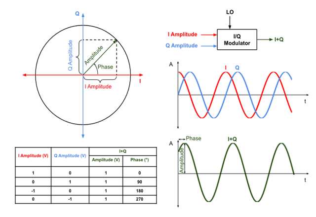
the phase for each IQ sample is.   p = atan2(Q/I),   (is this correct or not).


beside. the IQ samples's amptitude for each should be the same.  ( I[i]*I[i] +Q[i]*Q[i]) =. (I[j]*I[j]+Q[j]*Q[j]).  but the samples I got above does not satisfy this form. why and  how to understanding it.?

rgds

Parents Reply Children
  • Hi, Saleh:

           it's most excited to get the reply from you, and it's very useful for me to promote my project implemetation.

          for first about antenna array:  I have used oscillograph to catch the antenna gpio wave. which I get is totally matched as your guidance.  so this is fixed.

          and for the IQ samples format, I think I made the right understanding as you said. but still I got another confusion On the IQ samples which get from the reference period and sample slot。

          1. from the White Paper, I got the information that the reference period samples is used to calculate the frequency offset t between the transmitter and receiver。But I am wondering how to calculate this?could you give some directly method according to your experience.

    as my understanding about the IQ sampleing。within ideally environment, the raido signal send from transmitter during the CTE period keeps  as a stable frequency of sin/cos wave.  in the first guard time(for adjustment).  so the difference of the IQ samples we get  from the reference and sample slot is the sample frequency . and sample point is difference.

     actually I think the deep reason is  I cannot understanding the frequency offset between transmitter and receiver and influence of the offset would lead. could you please give me a clear words about this point.

         2. and the IQ wave when I use only on antenna, I got the same problem with this. but it seems still  not got a good solution.  AoA IQ data seem NOT uncorrect, when used one antenna? 

     Thank you, 

    Have a nice day. 

  • Hi Allen,

    1. from the White Paper, I got the information that the reference period samples is used to calculate the frequency offset t between the transmitter and receiver。But I am wondering how to calculate this?

    You can use the reference period as a reference for the received signal, and calculate the phase difference between each point and this reference part. Actually, we don't make any assumption about the absolute signal phase and everything is measured compared to this reference point. You know the CTE signal frequency (250KHz or 500KHz) and the time of each sample is taken, so you can calculate the phase difference of each sample with the reference one.

     2. and the IQ wave when I use only on antenna, I got the same problem with this. but it seems still  not got a good solution.  AoA IQ data seem NOT uncorrect, when used one antenna? 

    If the transmitter sends CTE on 2M PHY, then the captured CTE signal will be 500KHz, if 1M PHY is used, then would be 250 KHz. It means if you use a single antenna at the receiver side, by visualizing the received IQ samples, you should be able to see a sine wave (If it's set to 1M PHY, then you can see this better). Please take a look to the images sent on this question.

    Also you can change the sampling rate to the non standard values in order to capture the data faster and see the CTE signal smoothly. For example this line of code can be changed to RADIO_DFECTRL1_TSAMPLESPACING_125ns

    It would be a good idea to capture and draw the IQ samples using a single antenna, just to make sure you are receiving the IQ samples properly (it should be a sine wave).

Related