How to put the UART to sleep (low power mode)

I believe it started with SDK 2.0.0 but the board config files now define different ways to specify how hardware is to run.

&pinctrl {

    uart1_default: uart1_default {
		group1 {
			psels = <NRF_PSEL(UART_TX, 0, 26)>,
				<NRF_PSEL(UART_RTS, 0, 29)>;
		};
		group2 {
			psels = <NRF_PSEL(UART_RX, 0, 27)>,
				<NRF_PSEL(UART_CTS, 0, 28)>;
			bias-pull-up;
		};
	};

	uart1_sleep: uart1_sleep {
		group1 {
			psels = <NRF_PSEL(UART_TX, 0, 26)>,
				<NRF_PSEL(UART_RX, 0, 27)>,
				<NRF_PSEL(UART_RTS, 0, 29)>,
				<NRF_PSEL(UART_CTS, 0, 28)>;
			low-power-enable;
		};
	};
	
&uart1 {
	status = "okay";
	pinctrl-0 = <&uart1_default_alt>;
	pinctrl-1 = <&uart1_sleep_alt>;
	pinctrl-names = "default", "sleep";
};

I took this to mean that I can dynamically toggle these configurations from "uart1_default" to "uart1_sleep" from perhaps a function call. Did find the pinctrl_apply_state() function call but it's return a -2 that state id doesn't exist even though it is defined. Here's my code.

uart = device_get_binding("UART_1");
int err = pinctrl_apply_state(uart->config, PINCTRL_STATE_SLEEP); // Returns -2
Any ideas?
Parents Reply Children
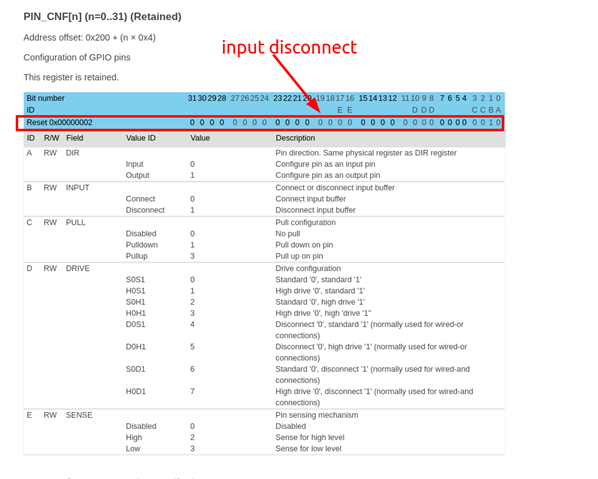
  • Yes, you should be able to reduce the sleep current to around 0.95 uA by entering System OFF mode. The important thing to ensure before entering this mode is that you don't have any floating inputs, as the GPIO configurations are preserved in this mode. Using the command "pm_device_action_run(<uart_dev>, PM_DEVICE_ACTION_SUSPEND);" will handle the pin configuration assigned to the UART interface. That is, set the pins as "input, disconnect" to prevent current leakge.

  • My apologies, I don't quite follow. Are you saying I should make a change to the below to indicate "input, disconnect"? I tried replacing low-power-enable; with input,disconnect but that doesn't compile.

    &pinctrl {

        uart0_default: uart0_default {
            group1 {
                psels = <NRF_PSEL(UART_TX, 0, 26)>,
                    <NRF_PSEL(UART_RTS, 0, 27)>;
            };
            group2 {
                psels = <NRF_PSEL(UART_RX, 0, 0)>,
                    <NRF_PSEL(UART_CTS, 0, 6)>;
                bias-pull-up;
            };
        };

        uart0_sleep: uart0_sleep {
            group1 {
                psels = <NRF_PSEL(UART_TX, 0, 26)>,
                    <NRF_PSEL(UART_RX, 0, 0)>,
                    <NRF_PSEL(UART_RTS, 0, 27)>,
                    <NRF_PSEL(UART_CTS, 0, 6)>;
                low-power-enable;
            };
        };
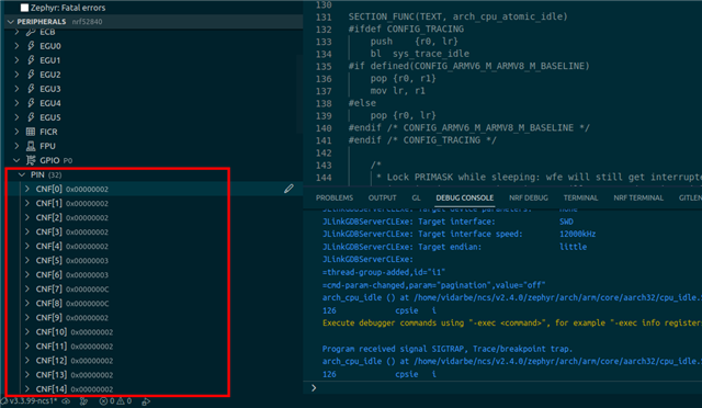
  • Sorry for not being clearer. No, you don't need to change anything for the UART. What I meant to point out is that there may be other pins not assigned to the UART that need to be configured as "input disconnect" as well. The easiest way to get an overview of all the pin configurations is probably by using the peripheral viewer in VS Code when you debug the application. You can place a breakpoint at the function where you enter system off to check what the GPIO configurations are at that point.

    The 'low-power-enable' property will make the pin control module configure the UARTE pins as input disconnect when the uart0_sleep group is applied via pm_device_action_run()->uarte_nrfx_pm_action() -> pinctrl_configure_pins()

    GPIO configurations viewed in VS code

    0x2 means the pin is configured as input disconnect and can safely be left floating. 

  • Except for the few pins setup for BLE Reset, none of the other GPIO pins are pinned out. In VS Code debugger, GPIO P0 and P1 pins have the value of 0x00000000. I assume that's ok.

  • Assume you meant 0x00000002. Either way, if there is a problem with the pin configurations, you should see that when you measure the current draw.

Related