Nordic nRF52840 flash readout is inconsistent.

Hello,

We are working on a project using the Nordic nRF52840. When flashing the unit it fails a flash-readout comparison check. This failure is inconsistent among different tries. Upon further investigation we also see 'corruption' occur at differnt locations in flash memory.
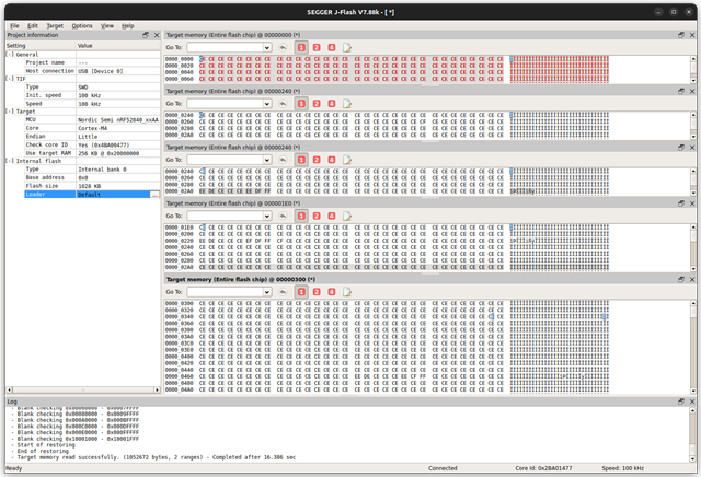
The image attached shows how readouts of the same registers (without any re-flashing) is different between each read.
Does anyone know what can produce this problem? and even better how to resolve this to create a stable product ?

(image)
the image show dummy data in red which is written to the flash, the bottom shows 4 readouts of the flash (without re-flashing)

(sidenotes)
- we make sure to erase the flash as stated in the datasheet
- this problem occurred only on 2 of the 5 boards we tested
- We checked different read-speeds as low as 100kHz to exclude hardware noise/crosstalk issues
- we've isolated the power supply to this chip as well
Parents
  • Hi,

    • What kind of debugger/programmer are you using?
    • Are you testing this on a custom board?
    • Have you looked at the SWD signals with a scope/logic analyzer? Since you get different readouts from the same chip after multiple tries, this seems to indicate a problem with the signal integrity.
    • What supply voltage are you running the device on? Is the signal level of the SWD lines at the same level as the supply voltage?

    Best regards,
    Jørgen 

Reply
  • Hi,

    • What kind of debugger/programmer are you using?
    • Are you testing this on a custom board?
    • Have you looked at the SWD signals with a scope/logic analyzer? Since you get different readouts from the same chip after multiple tries, this seems to indicate a problem with the signal integrity.
    • What supply voltage are you running the device on? Is the signal level of the SWD lines at the same level as the supply voltage?

    Best regards,
    Jørgen 

Children
  • Hi Jorgen,

    • we are using a segger J-link Compact
    • Our board is custom but our design is identical to configuration 5 w/o USB and NFC
    • We have not had the chance yet due to some equipment being temporarily unavailable, soonest that we can do this test will be Thursday
    • We are running it on 3V3 lab supply (isolated from all other power on the board) and the SWD signal level is also 3V3 as far as we know.

    I want to re-emphasize that this problem only near-consistently occurs on just 2 of the 5 boards.

    Kind Regards,
    David Enthoven

  • David-Enthoven said:
    we are using a segger J-link Compact

    How is the J-Link connected to the nRF52840? Please specify all pins/signals in use.

    David-Enthoven said:
    We have not had the chance yet due to some equipment being temporarily unavailable, soonest that we can do this test will be Thursday

    Please get the signals checked as soon as you have the equipment available.

    David-Enthoven said:
    We are running it on 3V3 lab supply (isolated from all other power on the board) and the SWD signal level is also 3V3 as far as we know.

    Have you tested other supply voltage levels if your board can handle that? Do they show same symptoms? The J-Link BASE Compact should support interface voltage levels between 1.2V to 5V on the SWD signal, given that the connections are done correctly, but would be good to get this confirmed.

    David-Enthoven said:
    I want to re-emphasize that this problem only near-consistently occurs on just 2 of the 5 boards.

    I noticed this, and it is also an indication to me that the signal integrity could be the source of this issue. Chip to chip variations in voltage of logic level of GPIO signals can cause marginal failures on some chips while others are working correctly, if the signal level is just below the expected threshold. 

Related