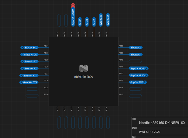
nRF9160 and nRF7002 Wi-Fi controller connection

I am in the process of designing a pcb with nRF9160 and nRF7002 to be able to use the network via LTE and / or Wi-Fi. In addition, I will use the GSM module for notifications.

I know that I must connect both modules (nRF7 and nRF9) with the QSPI bus, what about the nRF7 control signals?
The BUCKEN and HOST_IRQ pins are required and additionally I must have control over the time of switching on the voltage on the IOVDD pin in accordance with the documentation.
What about pins SW_CTR01, SW_CTRL1, COEX_GRANT, COEX_REQ, COEX_STATUS0? I know that they are used when we share the radio with bluetooth modules. Should I be concerned with them when connecting the nRF7 module to the nRF9 or should I leave them unconnected?

  • Hi Pawel,

    There is actually one sample using nRF7002EK with nRF9160DK for WiFi location service.

    nRF9160: Location — nRF Connect SDK 2.4.0 documentation (nordicsemi.com)

    There is only SPI connection between them and SW_CTR01, SW_CTRL1, COEX_GRANT, COEX_REQ, COEX_STATUS0 pins on nRF7002 are left in unconnected state.

    Best regards,

    Charlie

  • Thanks Charlie for the reply.


    I understand that the nRF7002EK overlay will solve the problem of turning on the power in hardware, but in my case I have to set the BUCKEN and VDIO pins at the right time?

    Best regards,

    Pawel

  • Hi Pawel,

    I think you can refer to Wi-Fi: Shell — nRF Connect SDK 2.4.0 documentation (nordicsemi.com), which provides full functions of WiFi based on nRF9160DK+nRF7002EK.

    The following files show how they are connected:

    nrf\boards\shields\nrf7002ek\nrf7002ek.overlay

    /* Copyright (c) 2023 Nordic Semiconductor ASA
     *
     * SPDX-License-Identifier: LicenseRef-Nordic-5-Clause
     */
    #include <freq.h>
    #include "nrf7002ek_coex.overlay"
    
    &arduino_spi {
    	status = "okay";
    	cs-gpios = <&arduino_header 16 GPIO_ACTIVE_LOW>; /* D10 */
    
    	nrf700x: nrf7002@0 {
    		compatible = "nordic,nrf700x-spi";
    		status = "okay";
    		reg = <0>;
    		spi-max-frequency = <DT_FREQ_M(8)>;
    
    		iovdd-ctrl-gpios = <&arduino_header 6 (GPIO_ACTIVE_HIGH | GPIO_PULL_DOWN)>;    /* D0 */
    		bucken-gpios = <&arduino_header 7 (GPIO_ACTIVE_HIGH | GPIO_PULL_DOWN)>;        /* D1 */
    		host-irq-gpios = <&arduino_header 13 GPIO_ACTIVE_HIGH>;     /* D7 */
    	};
    };
    

    nrf\samples\wifi\shell\boards\nrf9160dk_nrf9160_ns.overlay

    /*
     * Copyright (c) 2022 Nordic Semiconductor ASA
     *
     * SPDX-License-Identifier: LicenseRef-Nordic-5-Clause
     */
    
    /* Use high drive mode on SPI pins that handle communication with nRF7002
     * so that SCK frequency > 4 MHz can be used. */
    &spi3_default {
    	group1 {
    		nordic,drive-mode = <NRF_DRIVE_H0H1>;
    	};
    };
    
    /* Disabled because of conflicts on P0.00 and P0.01 - Arduino pins D0 and D1
     * (iovdd-ctrl-gpios and bucken-gpios in nrf7002ek_nrf7002, respectively). */
    &uart1 {
    	status = "disabled";
    };
    
    &arduino_header {
            gpio-map = <0 0 &gpio0 14 0>,
                       <1 0 &gpio0 15 0>,
                       <2 0 &gpio0 16 0>,
                       <3 0 &gpio0 17 0>,
                       <4 0 &gpio0 18 0>,
                       <5 0 &gpio0 19 0>,
                       <6 0 &gpio0 0 0>,
                       <7 0 &gpio0 1 0>,
                       <8 0 &gpio0 2 0>,
                       <9 0 &gpio0 3 0>,
                       <10 0 &gpio0 4 0>,
                       <11 0 &gpio0 5 0>,
                       <12 0 &gpio0 6 0>,
                       <13 0 &gpio0 7 0>,
                       <14 0 &gpio0 8 0>,
                       <15 0 &gpio0 9 0>,
                       <16 0 &gpio0 10 0>,
                       <17 0 &gpio0 11 0>,
                       <18 0 &gpio0 12 0>,
                       <19 0 &gpio0 13 0>,
                       <20 0 &gpio0 30 0>,
                       <21 0 &gpio0 31 0>;
    };
    

    Best regards,

    Charlie

  • Thanks for your help Charlie, now i understand.

    Best regards,

    Pawel

  • Hi Pawel,

    I am also trying to do the same.

    In 7002DK, Did you just solder the SB20-SB25 and used the QSPI pins via P24 header?

    Or did you remove the 0R Resistors R26-R31 also?

    Without removing the resistors, will it work? 

    Pls help.

    Thanks in advance.

Related