Antenna questions on nRF7002 - nRF5340

Hello everyone!
I'm developing a custom board in which the two above mentioned chip will live.

As the nRF7002 Prod. Spec file states, I can use two different antennas, one dedicated to the 5340, one to the 7002.

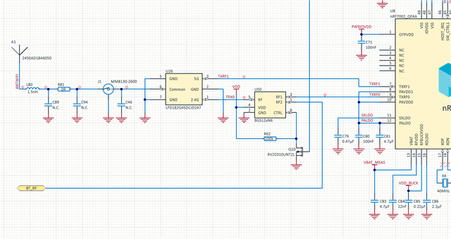
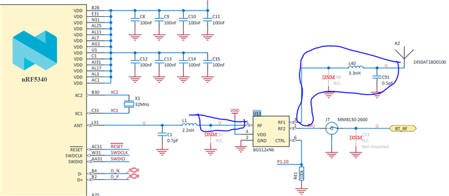
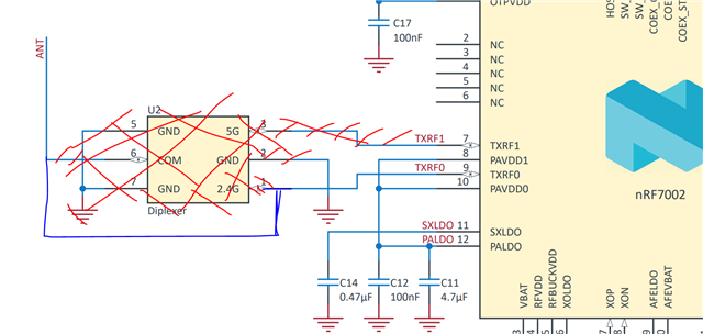
I already have a working design for a PCB antenna for the nRF5340, so that's not a problem. I'm more curious about the nRF7002, since my guess is that, if I want to use a patch antenna, I could only work with 2.4 OR 5 Ghz. This problem would be solved by the diplexer and the chip antenna as it is used in the nRF7002DK. Is the whole reasoning right? 

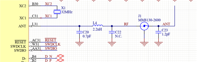
Also, If i decide to go for a PCB antenna for the 7002, what would be the RF trace that I need to adapt to 50 oHm impedance?

Do I need matching circuitry? If not, it's correct to assume that my antenna start directly from the PIN?

Parents
  • Hi,

    There are some designs for dual band PCB antennas, but they would require simulation to optimize the shape for both bands simultaneously. Using just one antenna is OK, but if you just want to use the 2.4GHz band it would be simplest just to share the antenna between the nRF5340 and the nRF7002. Both radios can't be transmitting simultaneously anyways so sharing the antenna is not a problem. If you want to try this you can use parts of the nRF7002 DK design files as reference, as the DK have a option to use the same 2.4GHz antenna for both radios:

    just remove the diplexter and connect the output of the RF switch to the antenna matching network directly.

    Do I need matching circuitry? If not, it's correct to assume that my antenna start directly from the PIN?

    You don't need a matching network for the nRF7002 side as the TXRF0 pin already have an impedance of 50 Ohm, but the antenna will require a matching network. The type of matching network is dependent on the type of antenna.

    The TXRF1 pin can just be left floating when not using 5GHz.


    Best regards,

    Bendik

  • Thank you for your answer.

    What do you mean that both can't be transmitting simultaneously even if I have different antennas? I thought it was not a problem since the antennas are different. I was planning to collect data from a set of devices via ESB (hence running in the network core) and forward them via WiFi (in the application core). Is there any problem with this?

  • I have one more question about this topic.

    The component U16 is the switch between the 5340 own antenna and the shared one with the 7002. This is controlled by GPIO 1 10 that in the devicetree I see its the btrf-switch-gpios field under the coex interface.

    Does this mean that in "regular" applications like normal BT, without having WiFi, let's say by default I should have a 2.4Ghz antenna that can interface directly with the 5340?

    Also, If I want to make my matching+patch antenna instead of using A2 as a chip antenna, should I control the impedance of the traces (inside the blue pen drawing) to be 50 ohms?

  • dario.sortino said:
    Does this mean that in "regular" applications like normal BT, without having WiFi, let's say by default I should have a 2.4Ghz antenna that can interface directly with the 5340?

    Yes, for boards without WiFI you would just connect the antenna directly to the nRF5340, with only the required radio and antenna matching networks in the RF path. Here is the nRF5340DK as a reference point:

    J1 is just a test connector it can be ignored.

    dario.sortino said:
    Also, If I want to make my matching+patch antenna instead of using A2 as a chip antenna, should I control the impedance of the traces (inside the blue pen drawing) to be 50 ohms?

    Yes, all transmission lines should have a controlled impedance of 50 Ohm.

  • Do you have an explanation for the Q10 transistor used to control the RF Swtich in the 7002 part of schematic (image in your first comment)

  • It's used for inverting the control signal from the nRF7002. The pull-up resistor R62 configures the RF switch to connect RF2 to RF by default. This is done to eliminate the need for crossing the RF traces. Which would be needed if the SW_CTRL0 pin of the nRF7002 is connected directly to the CTRL pin of the RF switch, as the switch would by default connect RF1 to RF.

  • Sorry for the late reply.

    So I assume that I can connect directly SW_CTRL0 to the CTRL pin of the RF switch, and have a devicetree overlay with

    	nrf_radio_coex: nrf7002-coex {
    		....
    		....
    		
    		swctrl1-gpios = <&gpio0 29 (GPIO_PULL_UP | GPIO_ACTIVE_LOW)>;
    		...
    		...
    		
    	};

    Am I correct?

Reply Children
Related