RTT works but Serial doesnt

As the title says, I'm struggling to make the serial interface work with nRF5240 CKAA

I'm using nRF52840DK for flashing the chip by using the P20 header to power and connect to the target (3V0, SWD CLK, SWD IO) and GND from outside the header.

As said, RTT connects by itself when automatically searching for it, but Serial communication doesn't work and I am not sure if  my settings are to blame.

I am using the 52840DK config to which I added this prj.conf

# Logger module
CONFIG_LOG=y

# Button and LED library
CONFIG_DK_LIBRARY=y

CONFIG_I2C=y

# Bluetooth LE
CONFIG_BT=y
# STEP 1 - Include the Peripheral Role support

CONFIG_BT_PERIPHERAL=y

# STEP 2 - Change the Bluetooth LE device name to Nordic_Peripheral
CONFIG_BT_DEVICE_NAME="TEST_UNIT_4"

# Increase stack size for the main thread and System Workqueue
CONFIG_SYSTEM_WORKQUEUE_STACK_SIZE=2048
CONFIG_MAIN_STACK_SIZE=2048

CONFIG_CLOCK_CONTROL_NRF_K32SRC_XTAL=n
CONFIG_CLOCK_CONTROL_NRF_K32SRC_RC=y

CONFIG_BOARD_ENABLE_DCDC=n

What am I missing?

Parents Reply Children
  • Oh. This I didn't know.

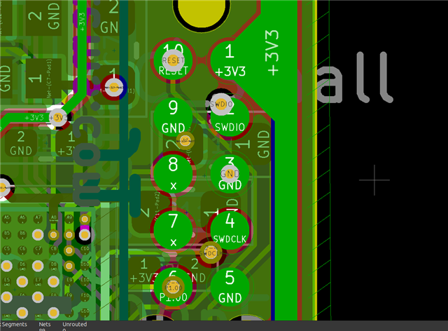
    We have a custom PCB with nRF52840, which connects to the DK via a JTAG cable


    I wish to know if P1.00 has anything to do with UART.

    Otherwise, I think there are not many options except for using RTT for now, as most of the other pins are not accessible anywhere else on this prototype.

  • Any GPIOs can be assigned to any serial interface on the nRF52840. By default, the UART TX pin is configured to GPIO P0.06, but this can be changed in the devicetree/overlay files when building a project in nRF Connect SDK.

  • That would be awesome. I am not using the Reset pin and the p1.00 for anything really. 

    For nRF5240 CKAA I am using, the Reset is K6 (P0.18) and P1.00/TraceData0 is J3

    So you think it's worthwhile attempting to switch those in software to perform as UART?

    If so, where should I connect them on the DK and will the UART to USB interface listen to the target's UART by itself?

    Also one more question, can you explain how RTT works? I assume it uses SWDIO and SWDCLK - what kind of protocol is it and is it parallel to UART?

    Thanks a lot for your support!

  • bem22 said:
    So you think it's worthwhile attempting to switch those in software to perform as UART?

    Yes, this should be simple to achieve. Create an overlay file where you configure the UART pins to P0.18 and P1.00. Make sure that CONFIG_GPIO_AS_PINRESET=n is set in the prj.conf file. Note that you need to do an eraseall operation (nrfjprog --eraseall) on the chip to disable the pinreset if it has been enabled by a previously programmed firmware.

    bem22 said:
    If so, where should I connect them on the DK and will the UART to USB interface listen to the target's UART by itself?

    Yes, you need to connect the configured UART pins on the external board to the UART pins on the DK (TX=P0.06, RX=P0.08). Also make sure that you erase any firmware present on the nRF52 chip on the DK (disconnect debug pins from external board and run "nrfjprog --eraseall").

    bem22 said:
    Also one more question, can you explain how RTT works? I assume it uses SWDIO and SWDCLK - what kind of protocol is it and is it parallel to UART?

    Real Time Transfer (RTT) is a technology provided by SEGGER. It uses the SWD interface to read/write data from a RAM buffer on the chip. RTT works separately from UART and is only available through the debug interface (SWD).

  • Thanks a lot, this was very useful.

    I tried googling around and also used GPT but couldn't figure out the actual way to set the pins.

    It seems like `rx-pin` and `tx-pin` are deprecated ways to setting the pins. 

    I read through the pin ctrl api but couldn't translate this to usable prj.cfg 

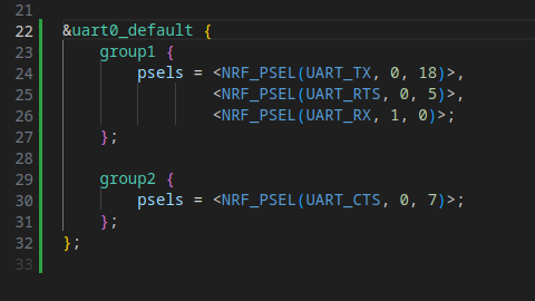
    I also tried to use the device tree interface to set the p0.18 and p1.00 as TX and RX with this result

    However, this doesn't allow me to change the default baud rate and add other options because groups can only be used for default nodes.

    Also, although I added CONFIG_GPIO_AS_PINRESET=n after eraseall operation and flashed again, I still get this message about pin reset whenever I flash. Is this related?

    So far I do not get any message back from UART. Is there anything else I have to enable?

    My full prj.cfg is this

    CONFIG_SYSTEM_WORKQUEUE_STACK_SIZE=2048
    CONFIG_MAIN_STACK_SIZE=2048
    
    CONFIG_HEAP_MEM_POOL_SIZE=1024
    CONFIG_MINIMAL_LIBC_MALLOC_ARENA_SIZE=2048
    
    CONFIG_BT=y
    CONFIG_BT_DEBUG_LOG=y
    CONFIG_BT_SMP=y
    CONFIG_BT_PERIPHERAL=y
    CONFIG_BT_DIS=y
    CONFIG_BT_BAS=y
    CONFIG_BT_DEVICE_NAME="Panorama Pipette"
    
    CONFIG_BT_SETTINGS=y
    CONFIG_FLASH=y
    CONFIG_FLASH_PAGE_LAYOUT=y
    CONFIG_FLASH_MAP=y
    CONFIG_NVS=y
    CONFIG_SETTINGS=y
    
    CONFIG_GPIO=y
    
    # I2C Module
    CONFIG_I2C=y
    
    # Logger module
    CONFIG_LOG=y
    
    
    CONFIG_CLOCK_CONTROL_NRF_K32SRC_XTAL=n
    CONFIG_CLOCK_CONTROL_NRF_K32SRC_RC=y
    
    # Disable DCDC regulator (DK property)
    CONFIG_BOARD_ENABLE_DCDC=n
    
    CONFIG_CONSOLE=y
    CONFIG_SERIAL=y
    CONFIG_UART_CONSOLE=y
    CONFIG_UART_INTERRUPT_DRIVEN=y
    
    CONFIG_GPIO_AS_PINRESET=n

Related