
Hello!
I am implementing the input of the key of the matrix structure of the circuit diagram below.
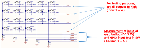
First of all, I tested whether the GPIO output (Row 1~4) and input (Column 1~5) are working normally.
- When all High outputs are given to Rows 1 to 4 and the button is pressed to confirm that signals are input to Columns 1 to 5, High signals are normally input to the Columns.
I confirmed that the " void bsp_event_handler(bsp_event_t event) " function was called.
/**@brief Function for handling events from the BSP module.
 *
 * @param[in]   event   Event generated by button press.
 */
void bsp_event_handler(bsp_event_t event)
{
    uint32_t err_code;
    uint8_t reason, result = 0;
    uint8_t mMatrix_souce;
   // NRF_UART0->TASKS_STARTRX= 1;
    //NRF_UART0->ENABLE = 1;
    printf("> bsp_event_handler ");

    //gMatrix_source = 1;
    /*
    mMatrix_souce = bsp_board_getMatrix_souce();
    if( ( eboards_Matrix_source_all_on == mMatrix_souce ) || ( eboards_Matrix_source_all_off == mMatrix_souce ) )
    {
        event = BSP_EVENT_KEY_5;
    }
    */

    switch (event)
    {

        case BSP_EVENT_KEY_0 :
            printf("BSP_E_KEY_0\r\n");
            break;

         case BSP_EVENT_KEY_1 :
            printf("BSP_E_KEY_1\r\n");
            break;

        case BSP_EVENT_KEY_2 :
            printf("BSP_E_KEY_2\r\n");
            break;

        case BSP_EVENT_KEY_3 :
            printf("BSP_E_KEY_3\r\n");
            break;

        case BSP_EVENT_KEY_4 :
            printf("BSP_E_KEY_4\r\n");
            break;

    }
}
[ PC Terminal ]
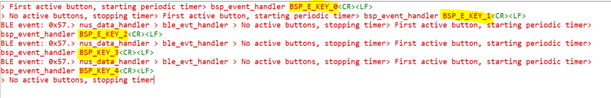
By sending data to PC through UART, it was confirmed that 5 Buttons were normally recognized.
---> question from here
The SW configuration for the matrix structure I thought of is as follows.
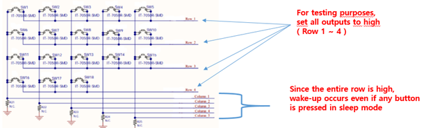
1) Before entering Sleep Mode, set all Rows 1 ~ 4 to High -> Wake-up occurs when any button is pressed in Sleep mode.
2) In the above test, it was confirmed that the handler functions are executed in the following order at wake-up.
static void gpiote_event_handler(nrf_drv_gpiote_pin_t pin, nrf_gpiote_polarity_t action) -> void bsp_event_handler(bsp_event_t event) ->
static void detection_delay_timeout_handler(void * p_context)
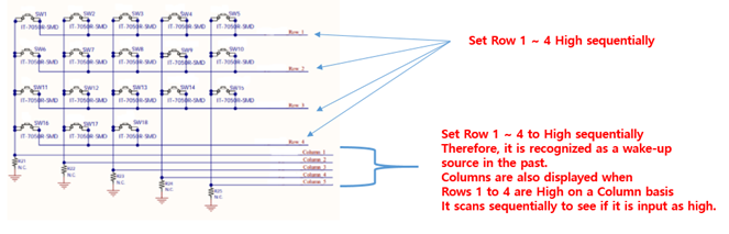
3) So, in the first static void gpiote_event_handler(nrf_drv_gpiote_pin_t pin, nrf_gpiote_polarity_t action) function,
Row 1 ~ 4 All High is set to High sequentially in the order of 1-> 2 -> 3 -> 4 -> to distinguish which button it actually is.
In the static void gpiote_event_handler(nrf_drv_gpiote_pin_t pin, nrf_gpiote_polarity_t action) function, make row high sequentially to distinguish which button was pressed.
The question is whether it is the right choice to try to distinguish in the void gpiote_event_handler(nrf_drv_gpiote_pin_t pin, nrf_gpiote_polarity_t action) function?
And if you have similar examples, please provide them.
tnank
