measurement of RSSI or transit time of a message via BLE with the Nordic 52840 and another slave board.

I have this problem, with a Nordic nRF52840 board I have to transmit a byte of known length, which I have to select a priori, and transmit it to a second slave evaluation board and then measure the RSSI value and the time it takes for the data packet to arrive depending on where the board is located, thus also going back to the distance value at which the two boards are located.
I would then also like to do the same thing with my android smartphone used as a slave.

I have tried to follow the examples I can find of nRF connect for desktop a bit, and in particular the codes available in visual studio code, but the standard codes there do not seem to answer my question.
Could you perhaps help me by explaining where to find an example code to modify to achieve this, and how to program the second board via the nRF52840?

thanks in advance!

Parents
  • Hi, 

    Using signal strength (RSSI) for estimating distance is not a reliable way for getting precise distance measurements. Since there are so many factors such as reflections and physical blocking affect the signal strength of the signal, hence the calculation of distance. I would suggest you consider this sample Bluetooth: nRF Distance Measurement with Bluetooth LE discovery which would also report RSSI value. Also, take a look at this post

    Regards,
    Amanda H.

  • Thank you Amanda for your reply.

    I have managed to get the two Nordic boards talking.
    Now what I would like to be able to do is to save the various RSSI, IFFT and RTT values in a file, so that I can then graph the time trend of these values.
    Can you please suggest a method for doing this?

    If there is a possibility, it would also be useful to save this file inside the nRF52840, so that I don't have to have it connected to the PC during measurements. And then later transfer those data saved in the non-volatile memory to the PC.

    Thank you again for your support!

  • Hello Amanda, thanks for your reply.

    The two boards communicate, but I have encountered a problem.
    I'll explain the hw and sw setup: one board is the nRF52840 which was loaded with the nrf_dm application, the other is the evaluation board BC840E which has the default program with which it was pre-loaded (so I didn't program it).

    I placed the two boards 1m apart, and for the 2.4 GHz frequency I should have a path loss of 40.04 dB.
    On the BC840E board I connected a 5 dBi gain antenna.
    Knowing that the nRF52840 in transmission I set it for 0 dBm and that the antenna gain on the nRF52840 is 0 dBi, I should see about -35 dBm of RSSI, the problem is that the measured RSSI is about -2 dBm.
    (if I don't put the external antenna on the BC840E the count doesn't add up, in fact I see rssi_openspace=199.53, which isn't correct anyway).

    I can't tell if I have misinterpreted the RSSI value, can you please clarify this for me?

    Thanks in advance!

  • Hi, 

    I would suggest programming both boards with the nrf_dm application and comparing the result of using two nRF52840DKs with the nrf_dm application.

    -Amanda H.

  • How can I copy the programme on the nRF52840 to the BC840E board as well?
    I have the 10-wire connector to connect the two boards, but then what do I have to do from VS Code?

    Can I directly connect the BC840-E to the computer and flash it from VS Code as I did with the nRF52840?

  • Hi, 

    Take a look at this post on how to set the sample for BC840E. 

    Leonardo Balocchi said:
    Can I directly connect the BC840-E to the computer and flash it from VS Code as I did with the nRF52840?

    According to https://www.mouser.com/datasheet/2/915/BlueNor_BC840_datasheets-1622924.pdf, A Nordic nRF52840 DK is recommended for programming this evaluation board.

    -Amanda H.

  • Hi Amanda, thanks again for your reply.
    I'm sorry, but I'm still not clear on the process for programming the BC840 E board.
    If you could tell me the exact steps to follow I would be very grateful.

    From the datasheet of the BC840E board I see that the following line of code must be written from the terminal (with the nRF52840 connected to the PC I imagine, and the other BC840E board connected both to the PC for power and to the nRF52840 with the 10 connection wires): nrfjprog -f NRF52 --program BT840_AT_3in1PC181113.hex --chiperase --reset

    However when I try to run this line from nrf Serial Terminal and having selected the nRF52840 device it tells me "Please connect a device". Also, how is the file I want to load specified? and more importantly, where is it taken from and how does the terminal find that file path?

    Could you explain to me step by step what to connect and how to do it? 

Reply
  • Hi Amanda, thanks again for your reply.
    I'm sorry, but I'm still not clear on the process for programming the BC840 E board.
    If you could tell me the exact steps to follow I would be very grateful.

    From the datasheet of the BC840E board I see that the following line of code must be written from the terminal (with the nRF52840 connected to the PC I imagine, and the other BC840E board connected both to the PC for power and to the nRF52840 with the 10 connection wires): nrfjprog -f NRF52 --program BT840_AT_3in1PC181113.hex --chiperase --reset

    However when I try to run this line from nrf Serial Terminal and having selected the nRF52840 device it tells me "Please connect a device". Also, how is the file I want to load specified? and more importantly, where is it taken from and how does the terminal find that file path?

    Could you explain to me step by step what to connect and how to do it? 

Children
  • Hi,

    Leonardo Balocchi said:
    From the datasheet of the BC840E board I see that the following line of code must be written from the terminal (with the nRF52840 connected to the PC I imagine, and the other BC840E board connected both to the PC for power and to the nRF52840 with the 10 connection wires): nrfjprog -f NRF52 --program BT840_AT_3in1PC181113.hex --chiperase --reset

    To run that command, you need to install nRF Command Line Tools.

    Guess you can program the BC840E directly without connecting nRF52840DK. You could try to program that image to see whether it can work or not.  

    To test the nrf_dm application for BC840E, refer to that post on the previous reply to add the config to the prj.conf, and then build/program via VS code. 

    -Amanda H.

  • I'm sorry Amanda, I still haven't managed to program the BC840E.
    I had already installed nRF command line tool, it is the first thing it makes me install following the nRF desktop installation tutorial.

    If I try to launch it by running the nrfjprog file it opens and closes the terminal for me, so I think this terminal is something that is already built into nRF desktop, and should not be opened separately.
    On the other hand, if I try to connect to the board from nRF serial terminal v1.1.0 (i.e. within nRF desktop) it tells me that no device is connected.

  • Hi, 

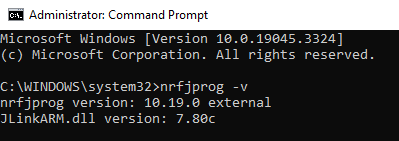
    Are you able to launch the nrfjprog by the Command Prompt and type "nrfjprog -v"? If so, you can program with that command provided by BC840E datasheet.

    You also could use nRF Connect Programmer to program the image. 

    -Amanda H.

  • Hi Amanda, thanks again.

    I tried connecting the BC840E to the PC and launching from the command line "C:\Users\leonardo\Documents\CHARM\nrf_dm_mod\build_1\zephyr>nrfjprog -f NRF52 --program zephyr.hex --chiperase --reset" (I moved to the path you see because it contains my zephyr.hex build result nrf_dm)

    however with only BC840E I get this error: "C:\Users\leonardo\Documents\CHARM\nrf_dm_mod\build_1\zephyr>nrfjprog -f NRF52 --program zephyr.hex --chiperase --reset
    ERROR: No debuggers were discovered.
    NOTE: For additional output, try running again with logging enabled (--log).
    NOTE: Any generated log error messages will be displayed.

    So I also connected the nRF52840 board to the PC and connected it to the BC840E via the 10 wires. This time the error disappeared: "C:\Users\leonardo\Documents\CHARM\nrf_dm_mod\build_1\zephyr>nrfjprog -f NRF52 --program zephyr.hex --chiperase --reset
    [ #################### ] 0.376s | Erase file - Done erasing
    [ #################### ] 1.997s | Program file - Done programming
    WARNING: A programming operation has been performed without --verify.
    WARNING: Programming can fail without error.
    Applying system reset.
    Run."

    However, I suspect that by doing this I am programming the nRF52840 board and not the BC840E board.
    And I also don't know how to verify that the BC840E was flashed with my zephyr.hex program correctly.

  • Hi, 

    The recommended way to program and debug nRF52-based products is using an nRF52 DK (an nRF52840 DK in your case), this is also stated in the BC840 datasheet, page.17. I have corrected my previous reply.

    Regards,
    Amanda H.  

Related