measurement of RSSI or transit time of a message via BLE with the Nordic 52840 and another slave board.

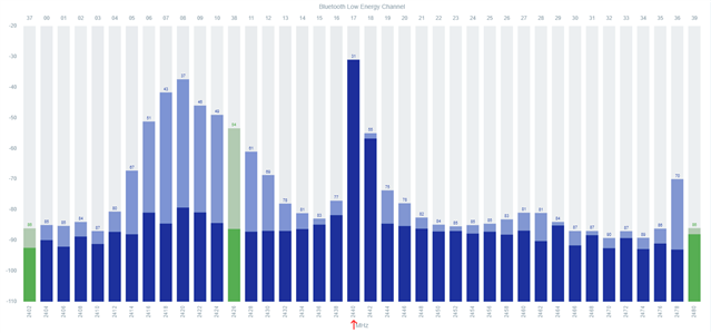
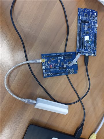
I have this problem, with a Nordic nRF52840 board I have to transmit a byte of known length, which I have to select a priori, and transmit it to a second slave evaluation board and then measure the RSSI value and the time it takes for the data packet to arrive depending on where the board is located, thus also going back to the distance value at which the two boards are located.
I would then also like to do the same thing with my android smartphone used as a slave.

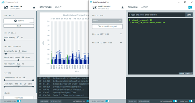
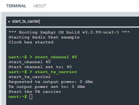
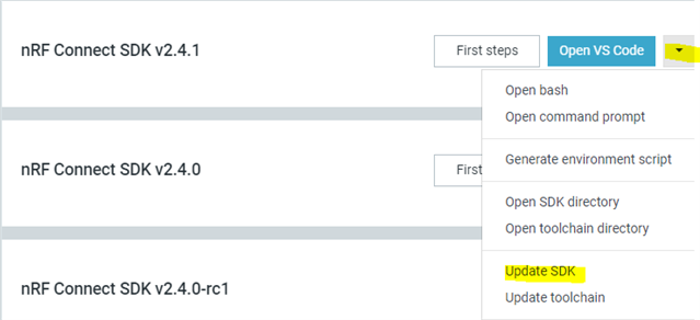
I have tried to follow the examples I can find of nRF connect for desktop a bit, and in particular the codes available in visual studio code, but the standard codes there do not seem to answer my question.
Could you perhaps help me by explaining where to find an example code to modify to achieve this, and how to program the second board via the nRF52840?

thanks in advance!

Parents
  • Hi, 

    Using signal strength (RSSI) for estimating distance is not a reliable way for getting precise distance measurements. Since there are so many factors such as reflections and physical blocking affect the signal strength of the signal, hence the calculation of distance. I would suggest you consider this sample Bluetooth: nRF Distance Measurement with Bluetooth LE discovery which would also report RSSI value. Also, take a look at this post

    Regards,
    Amanda H.

  • Thank you Amanda for your reply.

    I have managed to get the two Nordic boards talking.
    Now what I would like to be able to do is to save the various RSSI, IFFT and RTT values in a file, so that I can then graph the time trend of these values.
    Can you please suggest a method for doing this?

    If there is a possibility, it would also be useful to save this file inside the nRF52840, so that I don't have to have it connected to the PC during measurements. And then later transfer those data saved in the non-volatile memory to the PC.

    Thank you again for your support!

  • Hi,

    how can i check the register of the BC840E evaluation board? i can only connect to it via the nRF52840DK to load the programme, as you saw above.

  • However, I programmed the two boards as you told me, but the main problem persists:

    "I placed the two boards 1m apart, and for the 2.4 GHz frequency I should have a path loss of 40.04 dB.
    On the BC840E board I connected a 5 dBi gain antenna.
    Knowing that the nRF52840 in transmission I set it for 0 dBm and that the antenna gain on the nRF52840 is 0 dBi, I should see about -35 dBm of RSSI, the problem is that the measured RSSI is about -2 dBm."

  • Hi,

    As I mentioned in the first reply, RSSI is not the best way to do these types of measurements, there is often some interference or reflections that will change the expected results\outcome. Therefore, I suggest you use sample Bluetooth: nRF Distance Measurement with Bluetooth LE discovery which would also report RSSI value. Are you able to get the log with the sample?

    Our expert suspects that you are maybe not setting up the test correctly. For best results and most consistent I recommend that you use the Radio test sample, then select only one channel, like channel 40 as an example. Then put it in TX mode. This will give them a continuous +0dBm TX stream on channel 40. Then on the receiver side, connect nRF52840DK to the computer and then use the  RSSI Viewer app in nRF Connect for Desktop. You should be able to see what channel spikes when you enable the transmitter(BC840E board).  

    -Amanda H.

  • Hi Amanda, about your answer "I recommend that you use the Radio test sample, then select only one channel, like channel 40 as an example. Then put it in TX mode": To set the parameters you specified, do I have to act directly on the source code, or is there an easier way to do it?
    I read in the link you sent me about commands that can be entered via the user interface, but I didn't quite understand what it is and how I can use it.

    it is not possible to do this directly from nrf Connect Desktop?

    And when I try to insert the commands I found under "user interface" (for example print_rx or start_channel) in the link "Radio test (short range)" example you linked me, in the nrf Serial Terminal (nrf Desktop Connect tool), they do not work.

  • Hi,

    Leonardo Balocchi said:
    To set the parameters you specified, do I have to act directly on the source code, or is there an easier way to do it?

    Try to send the following commands on the top of the nRF Serial Terminal to do a modulated carrier at frequency 2440MHz: 

    start_channel 40

    start_tx_modulated_carrier 

    Then used an nRF52DK/nRF52840DK connected to the nRF RSSI viewer app (nRF Desktop Connect tool) to confirm that the DUT was transmitting. 


    You can see the 2440MHz channel rise up. 

    -Amanda H.

Reply
  • Hi,

    Leonardo Balocchi said:
    To set the parameters you specified, do I have to act directly on the source code, or is there an easier way to do it?

    Try to send the following commands on the top of the nRF Serial Terminal to do a modulated carrier at frequency 2440MHz: 

    start_channel 40

    start_tx_modulated_carrier 

    Then used an nRF52DK/nRF52840DK connected to the nRF RSSI viewer app (nRF Desktop Connect tool) to confirm that the DUT was transmitting. 


    You can see the 2440MHz channel rise up. 

    -Amanda H.

Children
  • Hi Amanda,

    I tried repeating the tests you told me, entering the sequence of commands (start_channel 40 and start_tx_modulated_carrier) but the result is not what I see in your photo.
    I attach a photo of the result I see:

  • Hi, 

    You should make sure the Radio test sample runs on your test target BC840E board and get the boot-up log as my figure. Then, type the commands and get the corresponding return.

    Amanda Hsieh said:

    Then, use a nRF52840DK to connect the nRF RSSI viewer app. 

    -Amanda H.

  • Hi Amanda,

    I tried to upload the example you described and which I found within the GitHub repository (github.com/.../radio_test.c ), as within the examples provided by NRF Connect in VS code, there is no radio_test example.
    Downloading it and doing "open an existing application" in VS Code gives the following errors during compilation:

    1) "No SOURCES given to Zephyr library: lib__libc__common".
    2) "implicit declaration of function 'NRFX_MHZ_TO_HZ' [-Wimplicit-function-declaration]"

    in the default code found on the net, without making any changes.
    How can I proceed to resolve these errors?
    The library mentioned in the error is also present in other applications that run without errors.
    It should also not be a folder location error.

    and also if I try to add the prj.conf file configuration in the building these errors pop up:

    1) sys/printk.h: No such file or directory

     2) #include errors detected based on information provided by the configurationProvider setting. Squiggles are disabled for this translation unit (C:\Users\leonardo\Downloads\sdk-nrf-master\sdk-nrf-master\samples\peripheral\radio_test\src\radio_cmd.c).

     3) cannot open source file "init.h"

     4) init.h: No such file or directory

     5) cannot open source file "shell/shell.h"

  • Hi, 

    Which NCS version are you using?

    The radio_test sample can be found under samples/peripheral/radio_test in the nRF Connect SDK folder structure.

    I would suggest you update the SDK via the Toolchain Manager and then load the radio_test sample from the NCS instead of downloading it from the web. 

    -Amanda H.

  • OK, I solved the update issue, now the building of the "radio_test" application seems to work.

    I remind you that I have 2 boards, the nRF52840 board and the BC840E evaluation board.
    I loaded the radio test programme into the nRF52840 board connected via USB to the PC, and using the "flash" in VS Code.
    To this first board the BC840E board is connected via a 10-wire connection (for the power supply the BC840E is not connected via USB to the pc, but to an external battery), and according to what you told me above, by flashing the programme to the nRF52840 connected via 10 wires to the BC840E, the same programme should also be loaded inside this second board.


    Then through the serial terminal I give the commands you wrote me above ("start_channel" 40 and "start_tx_modulated_carrier"), always with both boards connected as I described, but opening the serial terminal I see these writings printed:
    "bfdegeffcgfedd e!e "f#d$f%f&e'e(f)f*f+c,e-f.g/f0d1g2g3f4f5c6f7g8f9g:c;d<e=g>g?c@eAfBfCgDdEfFeGfHfIdJeKfLeMgNdOfPddffeedee d
    f
    f
    ceffgadfgfddedbgfe e!b "e#f$f%f&e'f(f)e*g+d,g-e.f/g0c1f2f3g4f5e6g7g8e9e:a;g<d=e>f?b@eAfBgCgDdEgFeGfHfIcJfKfLeMhNdOfPfehfeedcd e
    f"......

    The boud rate is correct and I have also tried flashing the board via the NRF Programmer, loading the file 'zephyr.hex' (always keeping the same configuration), instead by VS Code, but it produces the same result.

    That seems to be the correct way you described to me to programme the second BC840E board.

Related