Running CAN-BUS Sample with different shield (NRF52840DK & Seeed CAN BUS Shield V2.0)

Hi All, 

Im very new to this how firmware space and would love some help.

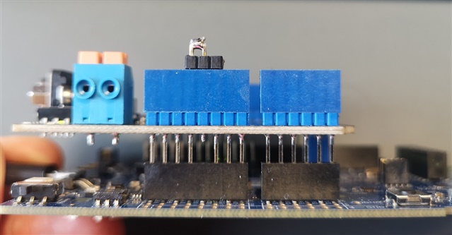
Currently i have a NRF52840 DK Board with a Seeed Canbus shield. (CAN-BUS Shield V2.0 | Seeed Studio Wiki)

From what i have read is very similar to the DFROBOT CanBus Shield. (Only changing the default pinout for the CS from D10 to D9)

- I have been able to succesfully comple and flash the firmware but i get the following error :

Error starting CAN controller [-5]

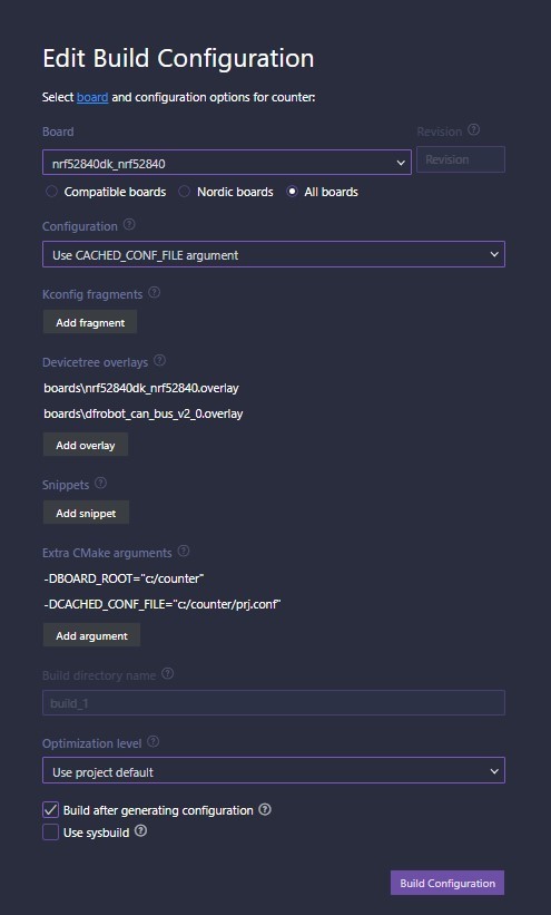
I have tried modifying the dfrobot_can_bus_v2_0.overlay to make it work with my seeed shield.  (changing the CS-GPIOS to 15 (D9) instead of 16 (D10).

The error remains the same, and i dont really know how to get a little bit more information to progress on this.

Im trying to run this sample: zephyr/samples/drivers/can/counter at main · zephyrproject-rtos/zephyr (github.com)

  • Hi 

    Sorry for not getting back to you. Even after so long in Nordic I keep overestimating the time I have available for these kinds of things....

    My next couple of weeks are pretty packed, but I will set aside some time for evaluating this the last month of May. I can't promise I will get to the bottom of it in the time available, but I will give it a go at least. I will send you an update once I start on the tests. 

    Best regards
    Torbjørn

  • thanks a lot. im subscribed to the thread but ill ping back :D

  • Sounds good, please reach out if you don't hear anything by that time Slight smile

  • Hi again

    As it happens I had some available time and decided to run a quick test with the Seeed Can-bus v2 shield. As we discussed earlier the voltage is definitely incorrect, but the shield seems to work fine when I cut the 5v line and make a short between the 3V3 and 5V signals on the Shield. 

    With this hack I can get the counter sample to run without any apparent issues, at least in the default loopback mode. 

    I use the following overlay:

    &arduino_spi {
    	status = "okay";
    	cs-gpios = <&arduino_header 15 GPIO_ACTIVE_LOW>; /* D9 */
    
    	mcp2515_dfrobot_can_bus_v2_0: can@0 {
    		compatible = "microchip,mcp2515";
    		spi-max-frequency = <1000000>;
    		int-gpios = <&arduino_header 8 0x1>; /* D2 */
    		status = "okay";
    		reg = <0x0>;
    		osc-freq = <16000000>;
    		bus-speed = <125000>;
    		sample-point = <875>;
    
    		can-transceiver {
    			max-bitrate = <1000000>;
    		};
    	};
    };
    
    / {
    	chosen {
    		zephyr,canbus = &mcp2515_dfrobot_can_bus_v2_0;
    	};
    };
    

    My 3.3V hack looks like this:

    Best regards
    Torbjørn

  • Hi everyone!

    I would like to know if you were able to communicate with another device via CAN using normal mode?

    I am working with the same board and the CAN BUS Seeed V2.0 shield so I followed the steps.

    I included the overlay you mentioned and also did the 3.3V hack as you indicated. With this I was able to make the Loopback mode work without problems sending and receiving frames as you can see below:

    [00:00:08.402,130] <inf> main: -------------------------
    [00:00:08.402,160] <inf> main: Initializing CAN bus
    [00:00:08.402,160] <inf> main: Asserting device ready.
    [00:00:08.402,191] <inf> main: CAN: Device can@0 ready.
    [00:00:08.402,191] <inf> main: -------------------------
    [00:00:08.402,221] <inf> main: Enabling MODE LOOPBACK.
    [00:00:08.402,221] <inf> main: MODE LOOPBACK.
    [00:00:08.402,221] <inf> main: -------------------------
    [00:00:08.402,252] <inf> main: Trying to set bitrate.
    [00:00:08.402,557] <inf> main: Bitrate set.
    [00:00:08.402,587] <inf> main: -------------------------
    [00:00:08.402,587] <inf> main: Adding reception filter
    [00:00:08.402,587] <inf> main: Before adding reception filter.
    [00:00:08.402,618] <inf> main: RX filter added successfully. Filter ID: 0
    [00:00:08.402,618] <inf> main: -------------------------
    [00:00:08.402,618] <inf> main: Trying to start CAN.
    [00:00:08.402,832] <inf> main: CAN started
    [00:00:08.402,832] <inf> main: -------------------------
    [00:00:08.402,832] <inf> main: Waiting for CAN frame
    [00:00:09.402,923] <inf> main: Sending CAN frame with ID: 0x7df, DLC: 8
    [00:00:09.403,228] <inf> main: CAN frame sent
    [00:00:09.403,228] <inf> main: ** ** ** ** ** ** ** **
    [00:00:09.403,808] <inf> main: Message sent successfully - Sender: Sender 1
    [00:00:09.403,808] <inf> main: tx_callback executed
    [00:00:11.403,320] <inf> main: Waiting for CAN frame
    [00:00:12.403,472] <inf> main: Sending CAN frame with ID: 0x7df, DLC: 8
    [00:00:12.403,747] <inf> main: CAN frame sent
    [00:00:12.403,778] <inf> main: ** ** ** ** ** ** ** **
    [00:00:12.404,296] <inf> main: Message sent successfully - Sender: Sender 1
    [00:00:12.404,327] <inf> main: tx_callback executed

    However, when I set the normal mode to receive or send frames I get the same error <err> main: Sending failed [-11] as you can see:

    [00:00:08.434,112] <inf> main: -------------------------
    [00:00:08.434,143] <inf> main: Initializing CAN bus
    [00:00:08.434,143] <inf> main: Asserting device ready.
    [00:00:08.434,173] <inf> main: CAN: Device can@0 ready.
    [00:00:08.434,173] <inf> main: -------------------------
    [00:00:08.434,204] <inf> main: Enabling MODE NORMAL.
    [00:00:08.434,204] <inf> main: MODE NORMAL.
    [00:00:08.434,204] <inf> main: -------------------------
    [00:00:08.434,234] <inf> main: Trying to set bitrate.
    [00:00:08.434,539] <inf> main: Bitrate set.
    [00:00:08.434,570] <inf> main: -------------------------
    [00:00:08.434,570] <inf> main: Adding reception filter
    [00:00:08.434,570] <inf> main: Before adding reception filter.
    [00:00:08.434,600] <inf> main: RX filter added successfully. Filter ID: 0
    [00:00:08.434,600] <inf> main: -------------------------
    [00:00:08.434,600] <inf> main: Trying to start CAN.
    [00:00:08.434,814] <inf> main: CAN started
    [00:00:08.434,814] <inf> main: -------------------------
    [00:00:08.434,814] <inf> main: Waiting for CAN frame
    [00:00:09.434,906] <inf> main: Sending CAN frame with ID: 0x7df, DLC: 8
    [00:00:09.435,211] <inf> main: CAN frame sent
    [00:00:09.435,211] <inf> main: ** ** ** ** ** ** ** **
    [00:00:11.435,302] <inf> main: Waiting for CAN frame
    [00:00:12.435,485] <inf> main: Sending CAN frame with ID: 0x7df, DLC: 8
    [00:00:17.435,607] <err> main: Sending failed [-11]
    [00:00:17.435,638] <inf> main: ** ** ** ** ** ** ** **
    [00:00:19.435,729] <inf> main: Waiting for CAN frame
    [00:00:20.435,913] <inf> main: Sending CAN frame with ID: 0x7df, DLC: 8
    [00:00:25.436,035] <err> main: Sending failed [-11]
    [00:00:25.436,065] <inf> main: ** ** ** ** ** ** ** **

    This is the code that i'm using:

    #include <zephyr/drivers/can.h>
    #include <zephyr/logging/log.h>
    LOG_MODULE_REGISTER(main);
    
    void tx_callback(const struct device *dev, int error, void *user_data)
    {
        char *sender = (char *)user_data;
    
        if (error != 0) {
            LOG_ERR("Sending failed [%d] - Sender: %s", error, sender);
        } else {
            LOG_INF("Message sent successfully - Sender: %s", sender);
        }
        LOG_INF("tx_callback executed");
    }
    
    int send_function(const struct device *can_dev)
    {
        struct can_frame frame = {.flags = 0, .id = 0x7df, .dlc = 8, .data = {0x02, 0x01, 0x0c, 0x00, 0x00, 0x00, 0x00, 0x00}};
    
        LOG_INF("Sending CAN frame with ID: 0x%x, DLC: %d", frame.id, frame.dlc);
    
        return can_send(can_dev, &frame, K_MSEC(5000), tx_callback, "Sender 1");
    }
    
    void rx_callback_function(const struct device *dev, struct can_frame *frame, void *user_data)
    {
        char *sender = (char *)user_data;
    
        LOG_INF("Received CAN frame - Sender: %s", sender);
        LOG_INF("ID: 0x%x, DLC: %d", frame->id, frame->dlc);
        LOG_HEXDUMP_INF(frame->data, frame->dlc, "Data: ");
    }
    
    int main(void)
    {
        LOG_INF("CanBus-OBD2 samplev11");
        int ret;
        k_sleep(K_MSEC(8000));
    
        LOG_INF("-------------------------");
    
        LOG_INF("Initializing CAN bus");
    
        const struct device *const can_dev = DEVICE_DT_GET(DT_CHOSEN(zephyr_canbus));
    
        LOG_INF("Asserting device ready.");
        if (!device_is_ready(can_dev)) {
            LOG_ERR("CAN: Device %s not ready.", can_dev->name);
            return 0;
        }
        LOG_INF("CAN: Device %s ready.", can_dev->name);
    
        LOG_INF("-------------------------");
    
        LOG_INF("Enabling MODE LOOPBACK.");
        ret = can_set_mode(can_dev, CAN_MODE_LOOPBACK);
        if (ret != 0) {
            LOG_ERR("Error setting CAN mode [%d]", ret);
            return 0;
        }
        LOG_INF("MODE LOOPBACK.");
    
        LOG_INF("-------------------------");
    
        LOG_INF("Trying to set bitrate.");
        ret = can_set_bitrate(can_dev, 500000);
        if (ret != 0) {
            LOG_ERR("Error setting CAN bitrate [%d]", ret);
            return 0;
        }
        LOG_INF("Bitrate set.");
    
        LOG_INF("-------------------------");
        LOG_INF("Adding reception filter");
    
        const struct can_filter my_filter = {
            .flags = CAN_FILTER_DATA, .id = 0x7E8, .mask = CAN_STD_ID_MASK};
        int filter_id;
    
        char *callback_arg = "Callback argument";
    
        LOG_INF("Before adding reception filter.");
        filter_id = can_add_rx_filter(can_dev, rx_callback_function, callback_arg, &my_filter);
        if (filter_id >= 0) {
            LOG_INF("RX filter added successfully. Filter ID: %d", filter_id);
        } else {
            LOG_ERR("Failed to add RX filter. Error code: %d", filter_id);
        }
        LOG_INF("-------------------------");
    
        LOG_INF("Trying to start CAN.");
        ret = can_start(can_dev);
        if (ret != 0) {
            LOG_ERR("Error starting CAN controller [%d]", ret);
            return 0;
        }
        LOG_INF("CAN started");
    
        LOG_INF("-------------------------");
    
        while (1) {
            LOG_INF("Waiting for CAN frame");
            k_sleep(K_MSEC(1000));
            ret = send_function(can_dev);
            if (ret != 0) {
                LOG_ERR("Sending failed [%d]", ret);
            } else {
                LOG_INF("CAN frame sent");
            }
            LOG_INF("** ** ** ** ** ** ** **");
            k_sleep(K_MSEC(2000)); // Intervalo de 2 segundos entre envíos
        }
    
        return 0;
    }
    

    Just in case, this is my build configuration:

    And my prj.config

    CONFIG_POLL=y
    CONFIG_CAN=y
    CONFIG_SPI=y
    CONFIG_CAN_MCP2515=y
    CONFIG_CAN_INIT_PRIORITY=80
    CONFIG_CAN_MAX_FILTER=5
    
    CONFIG_SHELL=y
    CONFIG_CAN_SHELL=y
    CONFIG_DEVICE_SHELL=y
    
    CONFIG_GPIO=y
    CONFIG_STATS=y
    CONFIG_STATS_NAMES=y
    CONFIG_STATS_SHELL=y
    CONFIG_CAN_STATS=y
    
    CONFIG_RTT_CONSOLE=n
    
    CONFIG_LOG=y
    CONFIG_CAN_LOG_LEVEL_DBG=y
    CONFIG_SPI_LOG_LEVEL_DBG=n
    
    CONFIG_PRINTK=y
    CONFIG_CONSOLE=y

    Any ideas? I really don't know if I am missing a file to include in the construction of my application. Also I was wondering if I could include a logic level converter (TXS0108E) to verify if the reason why i can't communicate is due to the difference of voltages in the SPI communication.

    I would be very grateful if you could help me :)

Related