Radio test of custom board

Hello all,

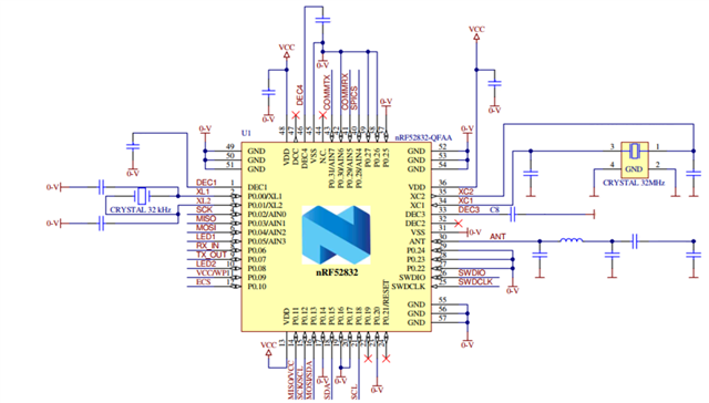
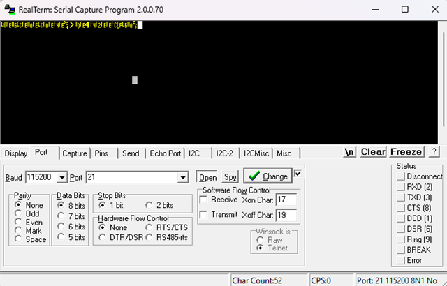
I want to run radio_test example on a custom board including nrf52832 chip. My custom board is programmed using a PCA10040 device kit. Now, I want to send standard commands in "https://infocenter.nordicsemi.com/index.jsp?topic=%2Fsdk_nrf5_v17.0.2%2Fnrf_radio_test_example.html". However, I don't have access to the custom board from puTTY terminal. It should be mentionaed that my custom board is connected to the device kit as follows:

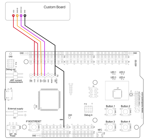
I want to ask what more shall I do to reach my custom board by puTTY?

Best regards,

Javad

  • Hi Javad,

    what IO pins do you have access to on your custom board? Did you layout some of the GPIOs as UART TX/RX? The radio test example (PuTTY in general) assumes that you are going to communicate through the UART comand line interface (CLI).

    If you have UART access, then you don't need the DK. Instead, the most efficient way to connect to UART, I think, would be through something like a "USB to TTL serial cable" (for example from Adafruit https://adafru.it/954, but any other brand will do).

    If all you have is the SWD interface, then your question is not "how to reach my custom board through PuTTY?" but "how to setup an adapter which translates UART (from PuTTY) to SWD, and then inside the nRF back from SWD into an UART interpretation?".

    For more on UART check out chapter 50 of the nRF52832 product specification.

    For more on the CLI: infocenter.nordicsemi.com/.../lib_cli.html

  • Dear All,

    Thanks for your replies. For your info, following is our schematic for custom board.

    As you can see, we selected pins 29 and 31 as Rx and Tx respectively. Then in the PCA10040.h file we modified pin number to meet our pinout requirements. When we use PuTTY and a USB to serial converters the typings are menningless as bellow:

    Do I need to modify everything else in UART configuration?

    As well, I've tried to debugg my custom board using J-Link RTT viewer through DK board and this has no output. 

    Best regards,

    Javad

  • Hi Javad,

    doesn't your schematics list RX and TX on pins 8&9?

    Anyway, I assume you're using the right data lines. And I also assume you've properly hooked up the USB's RX to the board's TX (and the TX<->RX, respectively). Oh, and that you're using a common ground.

    If the hardware matches the correct connections, then I would double check the required terminal settings. I'm not familiar with the software you're using, but for PuTTY you have to configure it as described here:

    infocenter.nordicsemi.com/.../lib_cli.html

    I my case, I've had a hard time until I realized that I forgot changing the backspace key to CTRL-H and the "function keys and keypad" to "SCO" (no idea what exactly those settings do, nor do I care much. I only know that my default settings at the time resulted in PuTTY freezing the transmission/receiption).

    Oh, one last thing: (at least with PuTTY) when you open the connection, you first have to (select the window, and then) press [Enter] to actually enter the uart_cli. Right after opening the connection, the new window remains black. After [Enter], it writes "uart_cli:~$"

    Best, Stefan

  • Dear Stefantk,

    Thank you for your reply and sorry for my late response. I was really busy these days. I've checked the settings in PuTTY and put all settings according to your recommendation and I still have problem.

    I think the problen rises anywhere else, because I've understood that this example uses CLI tool for UART communication and using a simple USB to serial converter and implementing an ordinary UART the commands are not interpreted correctly. Do tou have any recommendation how can I send command using a USB to serial converter while the CLI tool is used in UART communication in the example.

    Best regards,

    Javad

Related