nRF5340 and nRF21540 impedance matching circuits

Hi,

I am using a nRF5340 radio with a nRF21540 power amplifier in between the radio and the antenna.

I see there is a lot of support on Devzone for building pi matching circuits between the Nordic radios and antenna, due to antennas never being perfectly 50ohms.  By the same logic, do we need a pi matching circuit between the nRF5340 and nRF21540.  If so, are there standard recommended values and what is the best way to go about matching it?

Thanks in advance,

Chris

  • Hi, Chris!

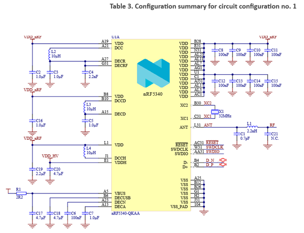
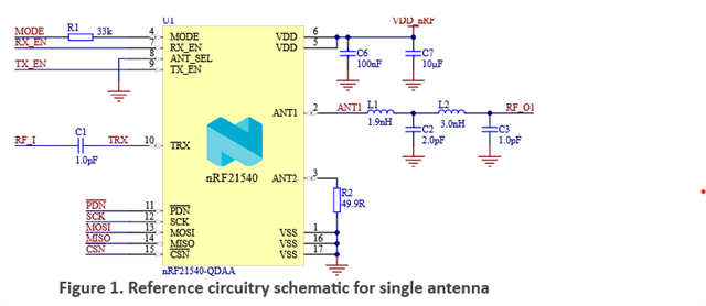
    You're right about that and we do have reference schematics for matching both the output of the nRF5340 (C1, L1, and C21 in reference circuitry) to 50 ohms and the input of the nRF21540 (C1 in reference circuitry) to 50 ohms. Screenshots of one configuration of the nRF5340 circuit and one configuration of the nRF21540 circuit follow for your convenience:

    For the nRF5340, C21 is marked as N.C., so in most cases C21 isn't necessary to include. If desired, you can send us your PCB when it is finished, to have the matching networks between the nRF5340 and the nRF21540, and between the nRF21540 and the antenna, tuned. This is a service we offer free of charge.

    When working on the layout later, remember to place the matching network close to the input/output it belongs to, and to make sure the transmission line between the devices is equal to 50 ohms.

    Best regards,
    Mathias

Related