nrf52840 high voltage mode

I have created a bare chip circuit with nrf52840-QIAA-R. The requirements were
1) It has to be powered by USB standalone and also a backup battery for which I have used a BQ24075 IC.
2) USB functionality is required
3) Internal DC-DC converter has to be enabled.

For this I have created the circuit and have also got it manufactured as well.
I am attaching the schematic below.
I have used high voltage mode of nRF and have connected VBUS from usb to VBUS pin of nrf and also have connected VDDH to VBUS as well and left VDD floating (with decoupling).


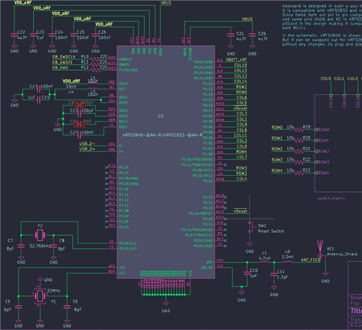
Note that the VBUS is supplied from the output of the charger IC BQ24075 (which is on another sheet). I have basically shorted VBUS to VDDH, used
LC filters and have enabled DC-DC converter in zephyr config.

As I power on the board it functions correctly and 1.8V default VDD is detected by programmer. I was also able to program it with a sample USB example to print HELLO world sample program of zephyr which printed Hello world to serial terminal over onboard USB connector. I also tried USB mass storage example with FAT file system and the device got identified on windows and was able to transfer files as well.

This is a pcb that is a custom keyboard whuch would use ZMK firmware which is an application built on top of zephyr.
I have defined my own device tree and flashed the firmware. But I am getting an error saying "zmk: FAILED TO SEND OVER USB: -19 "

I wanted to know whether this could be caused due to connecting VDDH and VBUS to same VBUS? Because I got most of the zephyr samples from zephyr to work on this custom board.

Link to github repo of zmk that I have forked: repo
This is the link to the devicetree that I use to build and flash zmk: DTS ( which is in the repo mentioned above in app/boards/arm/tr60)
I am also providing link to kicad project: kicad_project

I also tried the same application with exactly same code and same devicetree as mine on nrf52840dk and it worked. I am not able to understand why other USB samples work on my board but
not zmk application. Any thoughts

Thanks in advance.

Parents
  • Hi

    Did you get a HW review of the schematics and layout before manufacturing the board(s)? That's strongly recommended as it's easy to make mistakes without a second pair of eyes to look through what's been done. Since your application works on an nRF52840 DK, my initial thought is that this is a HW issue, but I can't find anything wrong with your schematics at least.

    The only things I can think of is that the 32 MHz and 32.768kHz crystals don't have the correct load capacitors. What are these rated as per the datasheet? Additionally I see you're using pins P0.09 and P0.10 as GPIOs in your design. These are NFCT pins by default, and needs to be configured as GPIOs with CONFIG_NFCT_PINS_AS_GPIOS = y in your project file.

    Best regards,

    Simon

  • Thanks simon,

    Yes I got my design reviewed (not from nordic) But from ZMK discoed group.
    I was able to use the USB functionality as it was a devicetree config issue and I have a series resistor issues.
    Thanks CONFIG_NFCT_PINS_AS_GPIOS this was useful

    My main question was that connecting VBUS and VDDH together to VBUS will cause any issue? As I cannot see any ref
    circuit with such a power pin config. As far as I can see VBUS is connected to VBUS and VDDH is connected to VEXT. But I have connected it to VBUS, since in my case VEXT is VBUS. would this cause any issue?

    And also I have the BQ IC output connected to both VBUS and VDDH. So, If I run the circuit with battery would the USB detect trigger as it receives voltage at VBUS and cause any issue with BLE functioning?

    Thanks.

Reply
  • Thanks simon,

    Yes I got my design reviewed (not from nordic) But from ZMK discoed group.
    I was able to use the USB functionality as it was a devicetree config issue and I have a series resistor issues.
    Thanks CONFIG_NFCT_PINS_AS_GPIOS this was useful

    My main question was that connecting VBUS and VDDH together to VBUS will cause any issue? As I cannot see any ref
    circuit with such a power pin config. As far as I can see VBUS is connected to VBUS and VDDH is connected to VEXT. But I have connected it to VBUS, since in my case VEXT is VBUS. would this cause any issue?

    And also I have the BQ IC output connected to both VBUS and VDDH. So, If I run the circuit with battery would the USB detect trigger as it receives voltage at VBUS and cause any issue with BLE functioning?

    Thanks.

Children
No Data
Related