
Hi all,
I'm quite new in Zephyr. Just to let you know ;P
I'm developing a code based on the nRF52832 in a custom board and I'd like to measure the voltage of two separate batteries.
These batteries are connected to a resistor voltage divider which is enabled or disabled by a digital switch. Here is the schema
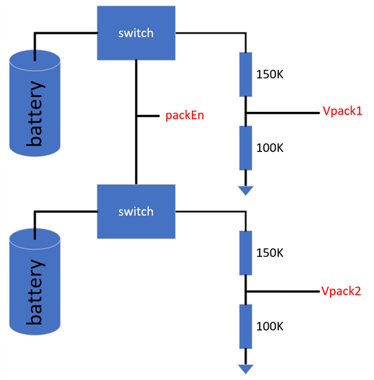
* packEn: 1 --> enables the two voltage dividers, 0--> disables the connection to the batteries
* Vpack1 --> Connected to AIN4
* Vpack2 --> Connected to AIN5
I'm using the nRF Connect SDK v2.4.1 with VS code.
In the main loop I read periodically the Vpack1 and Vpack2, but the values I get are random in most of the cases.
I'm sure that it's a configuration issue in the ADC, but I cannot find it, so I hope you can give a hand to find out what's the problem. Thank you.
This is my code:
#define HW_MAP_BAT_ENABLE_PIN				    NRF_GPIO_PIN_MAP(0, 30)
#define HW_MAP_BAT_R1_DIVIDER_VALUE		        150000.0f								//	Value in ohm
#define HW_MAP_BAT_R2_DIVIDER_VALUE	        	100000.0f								//	Value in ohm


#define	DRV_BAT_PACKS							2


typedef struct
{
	bool		valid;

	struct
	{
		bool	present;
		int16_t voltage;
	}pack[DRV_BAT_PACKS];

}drvBat_st;

static const struct device *adcDev =  DEVICE_DT_GET(DT_NODELABEL(adc));


#define	DRV_BAT_ADC_RESOLUTION						12
#define	DRV_BAT_ADC_GAIN							ADC_GAIN_1_3
#define	DRV_BAT_ADC_REFERENCE						ADC_REF_INTERNAL
#define	DRV_BAT_ADC_ADQUISITION_TIME				ADC_ACQ_TIME(ADC_ACQ_TIME_MICROSECONDS, 40)

#define DRV_BAT_ADC_PRIMARY_CHANNEL_ID 				4
#define DRV_BAT_ADC_PRIMRAY_CHANNEL_INPUT 			NRF_SAADC_INPUT_AIN4
#define DRV_BAT_ADC_SECONDARY_CHANNEL_ID 			5
#define DRV_BAT_ADC_SECONDARY_CHANNEL_INPUT 		NRF_SAADC_INPUT_AIN5


static const struct adc_channel_cfg primary = 	{
													.gain 				= DRV_BAT_ADC_GAIN,
													.reference 			= DRV_BAT_ADC_REFERENCE,
													.acquisition_time 	= DRV_BAT_ADC_ADQUISITION_TIME,
													.channel_id 		= DRV_BAT_ADC_PRIMARY_CHANNEL_ID,
													.differential		= 0,
													#if defined(CONFIG_ADC_CONFIGURABLE_INPUTS)
													.input_positive 	= DRV_BAT_ADC_PRIMRAY_CHANNEL_INPUT,
													#endif
												};

static const struct adc_channel_cfg secondary =	{
													.gain 				= DRV_BAT_ADC_GAIN,
													.reference 			= DRV_BAT_ADC_REFERENCE,
													.acquisition_time 	= DRV_BAT_ADC_ADQUISITION_TIME,
													.channel_id 		= DRV_BAT_ADC_SECONDARY_CHANNEL_ID,
													.differential		= 0,
													#if defined(CONFIG_ADC_CONFIGURABLE_INPUTS)
													.input_positive 	= DRV_BAT_ADC_SECONDARY_CHANNEL_INPUT,
													#endif
												};

static drvBat_st bat;


rc_t drvBat_Init (void)
{
	//
	//  Init the ADC channel configuration needed
	//

	static bool init = false;

	if ( true == init )
	{
		return RC_SUCCESS;
	}

	//	Configure adc channels used to measure battery voltage

	if ( 0 != adc_channel_setup(adcDev, &primary) )
	{
		return RC_ERROR;
	}

	if ( 0 != adc_channel_setup(adcDev, &secondary) )
	{
		return RC_ERROR;
	}

	//	Init battery power control

	nrfx_gpiote_out_config_t config = NRFX_GPIOTE_CONFIG_OUT_SIMPLE(false);
	nrfx_gpiote_out_init (HW_MAP_BAT_ENABLE_PIN, &config);											//	Configure battery control pin

	init = true;

	return RC_SUCCESS;
}


rc_t drvBat_Measure (void)
{
	//
	//
	//

	int16_t samples[2];

	const struct adc_sequence sequence = 	{
												.channels 		= BIT(DRV_BAT_ADC_PRIMARY_CHANNEL_ID) | BIT(DRV_BAT_ADC_SECONDARY_CHANNEL_ID) ,
												.buffer 		= samples,
												.buffer_size 	= sizeof(samples),
												.resolution 	= DRV_BAT_ADC_RESOLUTION,
												.oversampling 	= 0,					// don't oversample
												.calibrate 		= false					// calibrate
											};

	nrfx_gpiote_out_set(HW_MAP_BAT_ENABLE_PIN);											//	Enable the voltage divider

	k_msleep(DRV_BAT_ENABLE_TIMEOUT);													//	Little wait to ensure that voltage is stable before performing an adc read

	if ( 0 != adc_read(adcDev, &sequence) )
	{
		return RC_ERROR;
	}

	nrfx_gpiote_out_clear(HW_MAP_BAT_ENABLE_PIN);										//	Disable the voltage divider

	for (uint8_t i=0; i<DRV_BAT_PACKS; i++)
	{
		int32_t raw = (int32_t)samples[i];

		if ( 0 != adc_raw_to_millivolts(DRV_BAT_ADC_REFERENCE, DRV_BAT_ADC_GAIN, DRV_BAT_ADC_RESOLUTION, &raw) )
		{
			return RC_ERROR;
		}

		bat.pack[i].present = false;
		bat.pack[i].voltage = (int16_t)(raw / DRV_BAT_DIVIDER_FACTOR);

		if ( 0 > bat.pack[i].voltage )
		{
			bat.pack[i].voltage = 0;
		}

		if ( DRV_BAT_MIN_VOLTAGE <= bat.pack[i].voltage )
		{
			bat.pack[i].present = true;
		}
	}

	return RC_SUCCESS;
}
Thank you so much for your help
Ragards,
David

