SPI Clock issue on sample code


Hello 

i am using SPI sample code in sample code 1 MHZ clock using and check this pin on DSO and getting this type of clock which is mention in pic 1 but i want contineous
clock. can you guide me why getting this type of clock . Yellow line for clock 
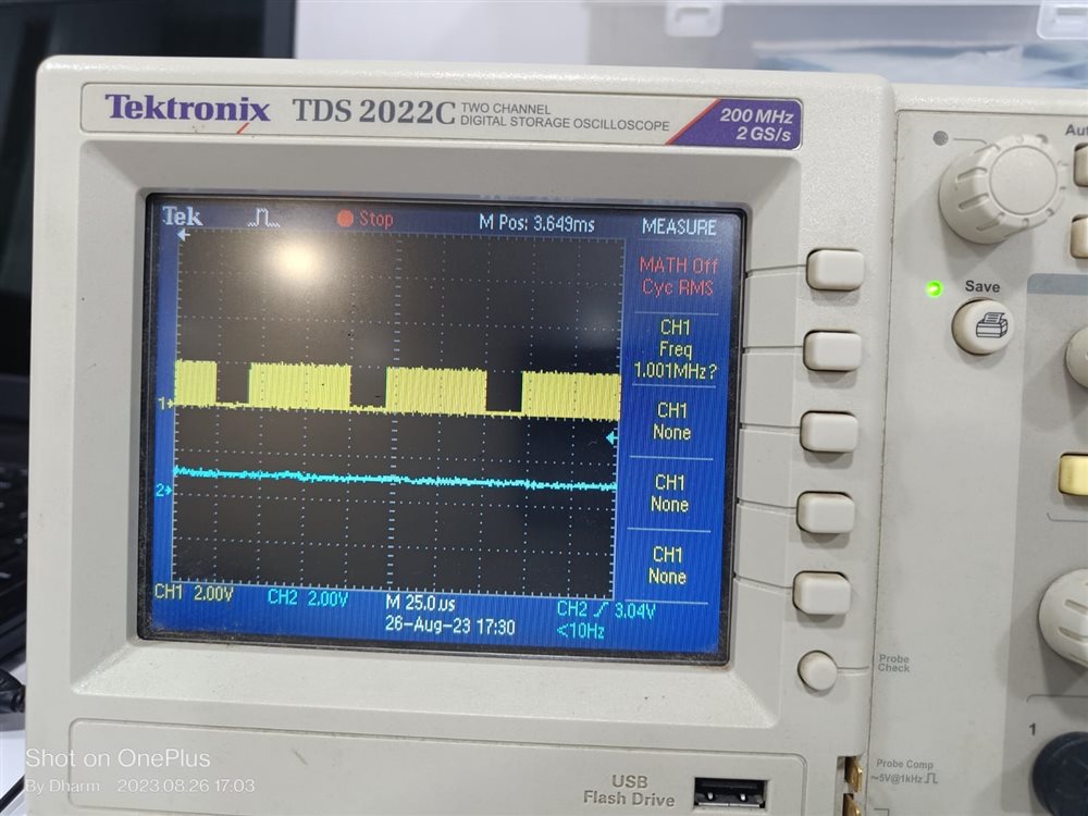
       Pic 1

1.The duration between two cycle is 25 micro Second

2..  clock  5 MHZ ( in pic 2 )
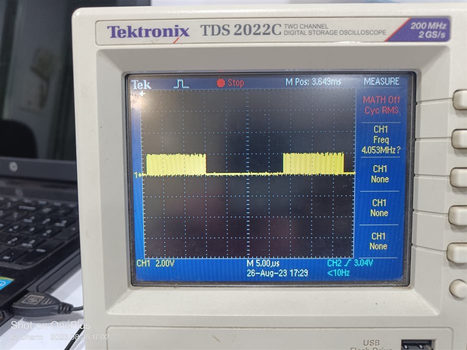
                 Pic 2 

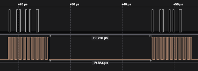
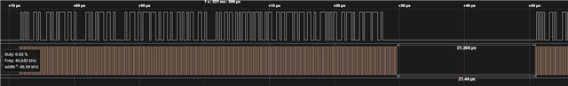
3 .According to Data sheet i want this type of clock which is mention in below picture

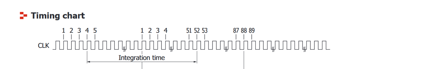
4 . my data will get on 87 th clock but in Pic 2 in one bunch i got 56 sub clock  

BR

DG

  • Hello

    Thank you for contacting DevZone at NordicSemi.

    I have been assigned this ticket; however, I was not able to work on it.

    I will look at it tomorrow and will come back to you accordingly.

    Regards,
    Naeem

  • Hello, 

    Thank you for your patience.

    It depends on what you are transferring in each spi-transfer.

    For example, I have a 4MHz spi frequency, and when transferring 3 Bytes of data in a continuous loop, this is what I get:

    But when I increase the data to be sent in each transfer, the number of clock cycles in each transfer increases accordingly for successful completion of the transfer. This is what I get in such a case:

    Regards,

    Naeem

  • Easy fix

    Let's assume from your post that as you see 56 clock edges that you are sending 7 bytes (7x8=56). For continuous clocking - let's assume 88 clocks - you require continuous clock transmission, which happens when the receive length is set to a higher value than the transmit length, so the receive length should be 11 bytes (8x11=88) plus the length of the expected data starting at clock edge 87.

    Summary: set transmit length to 7, receive length to 11 (plus length of expected data) and all will be well.

    The data required will be in the receive buffer with an offset of 11 bytes (from your notes); let's assume this is a photodiode array with 128 elements:

    uint8_t mTxBuffer[7] = {1,2,..}
    uint8_t mRxBuffer[11+128} = {0};
    
    // 128 bytes of Photodiode data is in mRxBuffer[11] to mRxBuffer[138]

    Use the ORC register to control the transmit byte values after the first 7 bytes; typically use 0x00 or 0xFF

Related