
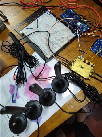
I am currently conducting experiments on direction finding using two nRF52833, one TX and the other as RX .
RX employs a 4PST (4-pole single-throw) RF switch for antenna switching. The logic for controlling the RF switch is achieved by toggling between high and low voltage.
I saw the following configuration in the nrf52833.overlay file, and I understand that this configuration is intended for use with antenna arrays designed by Nordic Semiconductor.
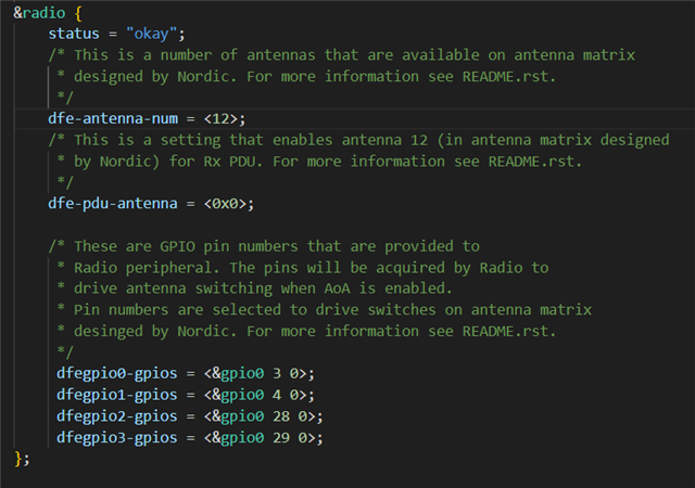
I have 2 question:
1. Could I use the provided configuration to control my RF SWITCH for antenna switching? If yes, what configurations should I modify for control? If not, do I have alternative methods to control my SWITCH?
2. Using an antenna array with four antennas, do I need to make modifications to the beam pattern for the following?
static const uint8_t ant_patterns[] = { 0x2, 0x0, 0x5, 0x6, 0x1, 0x4,
					0xC, 0x9, 0xE, 0xD, 0x8, 0xA };
#endif /* CONFIG_BT_DF_CTE_RX_AOA */
thanks for your help!

