Getting started with Bluetooth Direction Finding

Hello, i have several questions regarding bluetooth direction finding.

My ultimate goal is to have a Real Time Location System with 6 locators (AoA) and 30 trackers.


For now, i want to:

  1. be able to calculate an angle of arrival using nordic's example code
  2. be able to receive CTE signals from 2 trackers on the same locator
  3. implement a CTE beacon on my company's products whose firmware is based on nRF5 sdk v17

My questions are the following:

1 - What is the difference between Central/Peripheral and Locator/Beacon example codes ? Which would be the best for my use case?

2 - What is the link between the antennas and the Q/I samples? How does antenna switching work?

static void cte_recv_cb(struct bt_le_per_adv_sync *sync, struct bt_df_per_adv_sync_iq_samples_report const *report)
{
	char le_addr[BT_ADDR_LE_STR_LEN];
	
	struct bt_le_per_adv_sync_info info;
	bt_le_per_adv_sync_get_info(sync, &info);
	bt_addr_le_to_str(&info.addr, le_addr, sizeof(le_addr));

	char output[361]; 
    int offset = 0;
	for(int iter = 0; iter < report->sample_count; iter++)
	    offset += sprintf(output + offset,"%d;%d;", report->sample[iter].i, report->sample[iter].q);
	sprintf(output + offset,"\n");
	printk("%s;%s", le_addr, output);
}

I am able to display Q/I samples using the code above. However I cant make sense out of those values.
I went through the theory and I understand how AoA works and how to calculate the angle from Q/I values:

  • arctan(Q/I) gives me the phase of the signal (φ) received for each antenna
  • I then calculate the phase difference between 2 antennas Δφ
  • I measure the distance between 2 antennas (on nordic's antenna matrix that would be d = 5 cm for adjacent antennas)
  • the measured angle would be  θ = arcsin(λ/2π x Δφ  x 1/d)

But the result I get is random values roughly between -0.05 and 0.05.
I think my problem is antenna switching.
I am using the default pattern for nordic's antenna matrix:
(0x2, 0x0, 0x5, 0x6, 0x1, 0x40xC, 0x9, 0xE, 0xD, 0x8, 0xA) => ANT11, ANT12, ANT1, ANT2, ANT10, ANT3, ANT9, ANT4, ANT8, ANT7, ANT6, ANT5
I have 45 values for 12 antennas  so i assume that the first value is for ANT11, the second is for ANT12, ... and when i get to the thirteenth value, it loops back to ANT11.
This was my supposition and my measured angles seem off.
After digging a bit on this forum someone said that the code doesn't loop through all of the antennas, so im not sure.

3 - How can I receive CTE signals from multiple trackers on one locator?

(fyi i use nRF52833 DevKit and nrf example codes not zephyr's)
I ran the DF central code on a DevKit with a antenna matrix and i ran the DF peripheral code on two other DevKits.
Instead of getting CTE signals for both kits, it seems that the central would connect to only one of them and then only receive CTE signals from that same peripheral.
I thought that's how the example code was supposed to work so i tried running the 'connectionless' code (aka Locator/Beacon) but i get the same behaviour.

4 - Lastly I want to know if it is possible to implement a beacon in nRF5 sdk. And is it possible to do this while using the softdevice.

I want my products that already run on nRF5 sdk v17 (with softdevice) to be locatable.
I've seen a code posted on this forum by the support team that consists of ble_app_beacon example
where BLE_GAP_ADV_SET_DATA_SIZE_MAX is replaced by BLE_GAP_ADV_SET_DATA_SIZE_EXTENDED_MAX_SUPPORTED
and BLE_GAP_ADV_TYPE_NONCONNECTABLE_NONSCANNABLE_UNDIRECTED is replaced by BLE_GAP_ADV_TYPE_EXTENDED_NONCONNECTABLE_NONSCANNABLE_UNDIRECTED
but when i ran this code, i didnt receive Q/I values on my locator.

Thanks in advance

Parents
  • Hello,

    Sure thing.

    Let me start off by pointing you to the white paper we have available on direction finding. Off course I'll try to answer your questions here, but keep in mind that the whitepaper might be able to answer a lot on its own. It's definitely worth checking out.

    be able to calculate an angle of arrival using nordic's example code

    Sure thing! The white paper gives you the formulas you would need to use, and I would recommend you to have a look at our samples for this (here and here). 

    be able to receive CTE signals from 2 trackers on the same locator

    Yeah, that might require a bit more work, but is possible.

    implement a CTE beacon on my company's products whose firmware is based on nRF5 sdk v17

    That however is close to impossible. We have no support for direction finding in our nRF5 SDK. I would recommend you then to move on the nRF Connect SDK if you want this feature. Either way, moving to NCS might be a smart route, as there might not be any more updates coming to nRF 5 SDK

    1 - What is the difference between Central/Peripheral and Locator/Beacon example codes ? Which would be the best for my use case?

    Whether or not a BLE connection is used. What is best for your use-case depends on what it is. If the two devices are already connected and communicating for instance taking advantage of that already existing connection would be an idea.

    2 - What is the link between the antennas and the Q/I samples? How does antenna switching work?

    This is described in the whitepaper. By switching from one antenna to the other, we are getting another sample. It's the difference between multiple samples that we need, and in addition to that there is noise and multi-path issues that will affect the result, which requires us to have even more samples (and smart algorithms) to counteract.

    But the result I get is random values roughly between -0.05 and 0.05.

    What sample are you using to get this? Could you give me a plot of the entire CTE? If you for instance just look at some numbers from the reference period it might not make much sense.

    3 - How can I receive CTE signals from multiple trackers on one locator?

    Slightly more work involved with this. You would have to synchronize with multiple devices that do TX periodic advertising. Then you can distinguish provided IQ reports by Sync_Handle

    4 - Lastly I want to know if it is possible to implement a beacon in nRF5 sdk. And is it possible to do this while using the softdevice.

    It unfortunately isn't.

    Another thing I assume you are wondering about even though you haven't asked, is if we are providing an angle algorithm. We are not, unfortunately. Making a good angle algorithm also requires a bit of work, simply using the equations might not be enough. You can for instance have a look at this.

    Regards,

    Elfving

Reply
  • Hello,

    Sure thing.

    Let me start off by pointing you to the white paper we have available on direction finding. Off course I'll try to answer your questions here, but keep in mind that the whitepaper might be able to answer a lot on its own. It's definitely worth checking out.

    be able to calculate an angle of arrival using nordic's example code

    Sure thing! The white paper gives you the formulas you would need to use, and I would recommend you to have a look at our samples for this (here and here). 

    be able to receive CTE signals from 2 trackers on the same locator

    Yeah, that might require a bit more work, but is possible.

    implement a CTE beacon on my company's products whose firmware is based on nRF5 sdk v17

    That however is close to impossible. We have no support for direction finding in our nRF5 SDK. I would recommend you then to move on the nRF Connect SDK if you want this feature. Either way, moving to NCS might be a smart route, as there might not be any more updates coming to nRF 5 SDK

    1 - What is the difference between Central/Peripheral and Locator/Beacon example codes ? Which would be the best for my use case?

    Whether or not a BLE connection is used. What is best for your use-case depends on what it is. If the two devices are already connected and communicating for instance taking advantage of that already existing connection would be an idea.

    2 - What is the link between the antennas and the Q/I samples? How does antenna switching work?

    This is described in the whitepaper. By switching from one antenna to the other, we are getting another sample. It's the difference between multiple samples that we need, and in addition to that there is noise and multi-path issues that will affect the result, which requires us to have even more samples (and smart algorithms) to counteract.

    But the result I get is random values roughly between -0.05 and 0.05.

    What sample are you using to get this? Could you give me a plot of the entire CTE? If you for instance just look at some numbers from the reference period it might not make much sense.

    3 - How can I receive CTE signals from multiple trackers on one locator?

    Slightly more work involved with this. You would have to synchronize with multiple devices that do TX periodic advertising. Then you can distinguish provided IQ reports by Sync_Handle

    4 - Lastly I want to know if it is possible to implement a beacon in nRF5 sdk. And is it possible to do this while using the softdevice.

    It unfortunately isn't.

    Another thing I assume you are wondering about even though you haven't asked, is if we are providing an angle algorithm. We are not, unfortunately. Making a good angle algorithm also requires a bit of work, simply using the equations might not be enough. You can for instance have a look at this.

    Regards,

    Elfving

Children
  • Hi
    Thanks for your answer and sorry for the late reply
    I'm taking a look into your algorithm.

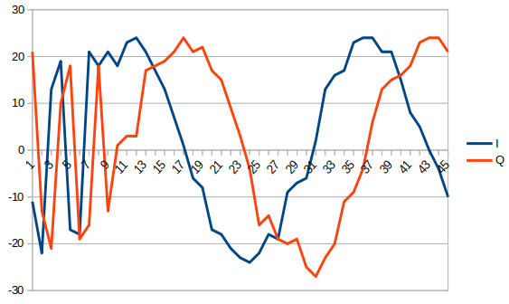
    This is a plot of the 45 samples of the CTE (including the reference period)

    It looks 'pretty' apart from the reference period but i wasn't expecting to see a smooth sine function when i plot the signal received by the 12 antennas. Am I not switching antennas or is this normal ?

  • Hi, plotting IQ data like this will never provide any information about the incoming signal. You need to transform the data into phase/amplitude and look at the phase data. And do remember that the sampling interval for the reference period is much lower than for the antenna switch period so printing it like above will look incorrect again.

    This has been discussed in quite a few cases earlier so I recommend searching and reading up on these.

  • Hi
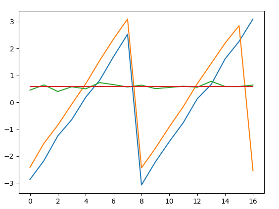
    I got some IQ samples switching between two adjacent antennas
    I then calculated the phase for each antenna

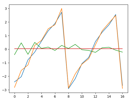
    In the image above,

    the blue line represents the phase of the first antenna
    the orange line represents the phase of the second antenna
    the green line represents the phase difference between the two antennas
    the red line is the average phase difference of throughout the whole signal

    my problem is that the phase difference is always below 1. Is this normal?
    because in theory it should range from -pi to +pi right?

  • That depends on what you are measuring. If you have one transmitter in a static position compared to the AoA receiver and use 2 antennas then the phase difference between the 2 antennas should be constant forever. So the flatter the line, the better.

    When you measure this phase shift between multiple antennas, then you can calculate the angle of the incoming signal.

    If the transmitter is moving relative to the AoA receiver antenna, then the phase shift can change with the movement, it will then depend how the movement is in relation to both antennas.

    If you set up an excel sheet where you calculate the distance from the transmitter to each of the AoA receiver antenna, then you can calculate the resulting phase for each of the antennas and you can model how the phase will change when you move the transmitter around.


  • Right now i have my antenna matrix sitting on a table and i am moving around it with my beacon devkit.
    i get my Q/I samples;
    i separate those samples according my antenna switching pattern;
    i calculate the phase with the formula 'phase = atan2(Q, I)';
    and finnaly, i calculate the difference between both waves and i display it on these graphs


    when i stand right in front of the antennas i get 0 rad phase difference as you can see in this graph which is logical since the signal reaches both antennas at the same time.

    in theory, if i am 'aligned' with the antennas, i should get +3.14 or -3.14 phase difference since the waves received by each antenna are in phase opposition

    however, when i move around, i cant get past 1rad phase difference (as shown in the other graph)

Related