Getting started with Bluetooth Direction Finding

Hello, i have several questions regarding bluetooth direction finding.

My ultimate goal is to have a Real Time Location System with 6 locators (AoA) and 30 trackers.


For now, i want to:

  1. be able to calculate an angle of arrival using nordic's example code
  2. be able to receive CTE signals from 2 trackers on the same locator
  3. implement a CTE beacon on my company's products whose firmware is based on nRF5 sdk v17

My questions are the following:

1 - What is the difference between Central/Peripheral and Locator/Beacon example codes ? Which would be the best for my use case?

2 - What is the link between the antennas and the Q/I samples? How does antenna switching work?

static void cte_recv_cb(struct bt_le_per_adv_sync *sync, struct bt_df_per_adv_sync_iq_samples_report const *report)
{
	char le_addr[BT_ADDR_LE_STR_LEN];
	
	struct bt_le_per_adv_sync_info info;
	bt_le_per_adv_sync_get_info(sync, &info);
	bt_addr_le_to_str(&info.addr, le_addr, sizeof(le_addr));

	char output[361]; 
    int offset = 0;
	for(int iter = 0; iter < report->sample_count; iter++)
	    offset += sprintf(output + offset,"%d;%d;", report->sample[iter].i, report->sample[iter].q);
	sprintf(output + offset,"\n");
	printk("%s;%s", le_addr, output);
}

I am able to display Q/I samples using the code above. However I cant make sense out of those values.
I went through the theory and I understand how AoA works and how to calculate the angle from Q/I values:

  • arctan(Q/I) gives me the phase of the signal (φ) received for each antenna
  • I then calculate the phase difference between 2 antennas Δφ
  • I measure the distance between 2 antennas (on nordic's antenna matrix that would be d = 5 cm for adjacent antennas)
  • the measured angle would be  θ = arcsin(λ/2π x Δφ  x 1/d)

But the result I get is random values roughly between -0.05 and 0.05.
I think my problem is antenna switching.
I am using the default pattern for nordic's antenna matrix:
(0x2, 0x0, 0x5, 0x6, 0x1, 0x40xC, 0x9, 0xE, 0xD, 0x8, 0xA) => ANT11, ANT12, ANT1, ANT2, ANT10, ANT3, ANT9, ANT4, ANT8, ANT7, ANT6, ANT5
I have 45 values for 12 antennas  so i assume that the first value is for ANT11, the second is for ANT12, ... and when i get to the thirteenth value, it loops back to ANT11.
This was my supposition and my measured angles seem off.
After digging a bit on this forum someone said that the code doesn't loop through all of the antennas, so im not sure.

3 - How can I receive CTE signals from multiple trackers on one locator?

(fyi i use nRF52833 DevKit and nrf example codes not zephyr's)
I ran the DF central code on a DevKit with a antenna matrix and i ran the DF peripheral code on two other DevKits.
Instead of getting CTE signals for both kits, it seems that the central would connect to only one of them and then only receive CTE signals from that same peripheral.
I thought that's how the example code was supposed to work so i tried running the 'connectionless' code (aka Locator/Beacon) but i get the same behaviour.

4 - Lastly I want to know if it is possible to implement a beacon in nRF5 sdk. And is it possible to do this while using the softdevice.

I want my products that already run on nRF5 sdk v17 (with softdevice) to be locatable.
I've seen a code posted on this forum by the support team that consists of ble_app_beacon example
where BLE_GAP_ADV_SET_DATA_SIZE_MAX is replaced by BLE_GAP_ADV_SET_DATA_SIZE_EXTENDED_MAX_SUPPORTED
and BLE_GAP_ADV_TYPE_NONCONNECTABLE_NONSCANNABLE_UNDIRECTED is replaced by BLE_GAP_ADV_TYPE_EXTENDED_NONCONNECTABLE_NONSCANNABLE_UNDIRECTED
but when i ran this code, i didnt receive Q/I values on my locator.

Thanks in advance

Parents
  • Hi again

    I'm reviving this ticket because i am still stuck
    Here is what i did.

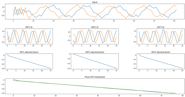
    I configured the sample code to work with a 3 antenna switch pattern.
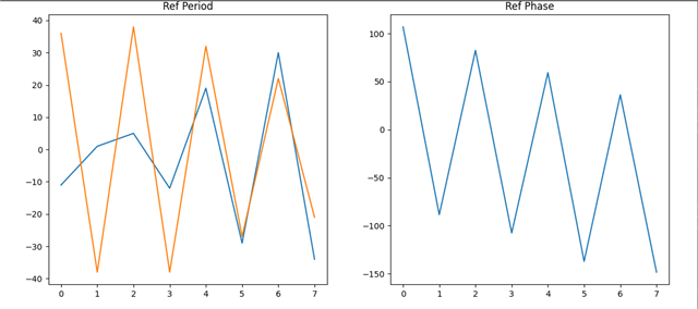
    As you can see the 1st signal 'looks' good. We can see the Ref period and some irregularities from antenna switching on the signal.

    Then i split the samples from each antenna  (2nd row of plots)

    I calculate the phase, and adjust to avoid having +/- pi jumps (3rd row of plots)

    I interpolate to take into account the time shift caused by the antenna switching (4th row of plots)

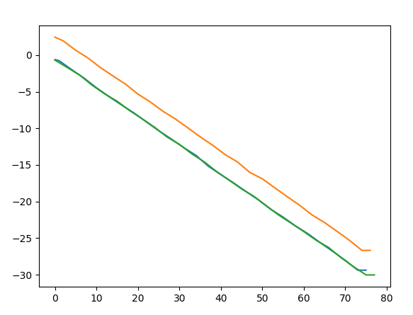
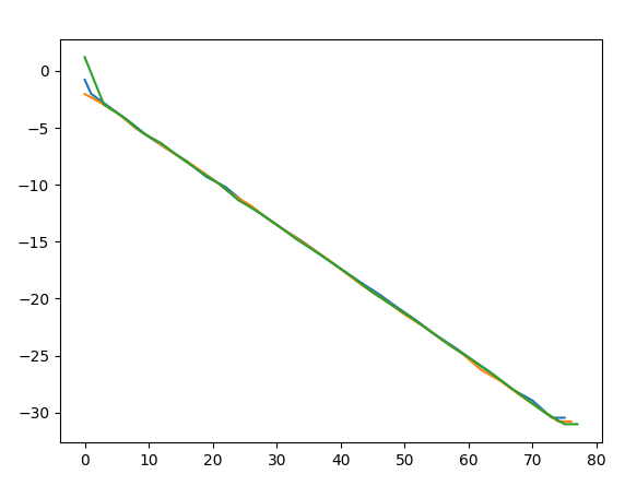
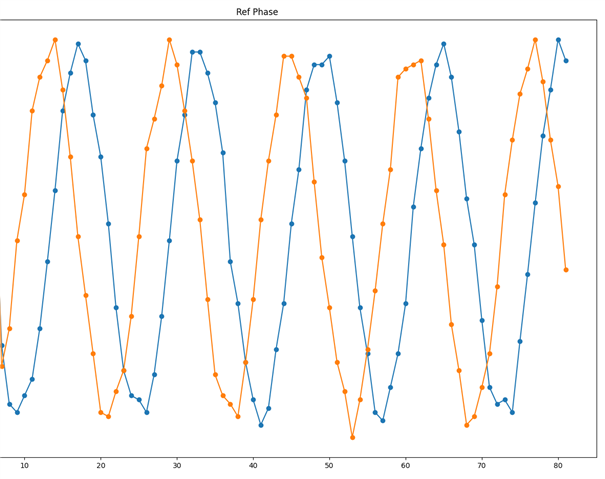
    But when i plot the phase difference, i get different results event if my beacon doesn't move.
    Here you can see the phases of ANT7 ANT8 and ANT9 in two different CTE signals after measuring the position of a static beacon


  • I am not sure I understand what you are trying to plot here.

    If you want to look at the samples you should do that with time on the X-axis and not the sample number, difficult to say what you are showing. This as the reference period has a different sampling interval than the rest of the samples.

    You would then use the reference period samples to predict the phase of the signal on the reference antenna for the entire sampling window. When you then start sampling the different antennas, you compare them to this predicted phase. For the samples with the reference antenna, the error should be 0. If it is not then the prediction is not good enough. The "error" on the other antennas will be the phase shift. If you do this then the phase will be around 0 so any phase shifts will be significantly easier to see than what seems to be in your graphs.

  • Also note that the further away from the antenna you are, the smaller the phase shift will be. This as you are measuring the difference in length from the transmitter to the different patches. This will basically set the limit where you can reliably measure the angle. I suggest testing with static transmitter at different distances as that should give you a clearer idea on how the angles/distance impacts the measured phase changes. When you have this under control, then you can start looking at moving objects.

  • sample count: 82, channel_idx: 29, number_of_antennas: 3
    sample count: 82, channel_idx: 0, number_of_antennas: 3
    sample count: 82, channel_idx: 0, number_of_antennas: 3
    sample count: 82, channel_idx: 0, number_of_antennas: 3
    sample count: 82, channel_idx: 0, number_of_antennas: 3
    sample count: 82, channel_idx: 17, number_of_antennas: 3
    sample count: 82, channel_idx: 0, number_of_antennas: 3
    sample count: 82, channel_idx: 0, number_of_antennas: 3
    sample count: 82, channel_idx: 0, number_of_antennas: 3
    sample count: 82, channel_idx: 0, number_of_antennas: 3
    sample count: 82, channel_idx: 28, number_of_antennas: 3
    sample count: 82, channel_idx: 0, number_of_antennas: 3
    sample count: 82, channel_idx: 0, number_of_antennas: 3
    sample count: 82, channel_idx: 0, number_of_antennas: 3
    sample count: 82, channel_idx: 0, number_of_antennas: 3
    sample count: 82, channel_idx: 31, number_of_antennas: 3
    sample count: 82, channel_idx: 0, number_of_antennas: 3
    sample count: 82, channel_idx: 0, number_of_antennas: 3
    sample count: 82, channel_idx: 0, number_of_antennas: 3
    sample count: 82, channel_idx: 0, number_of_antennas: 3
    sample count: 82, channel_idx: 35, number_of_antennas: 3
    sample count: 82, channel_idx: 0, number_of_antennas: 3
    sample count: 82, channel_idx: 0, number_of_antennas: 3
    sample count: 82, channel_idx: 0, number_of_antennas: 3
    sample count: 82, channel_idx: 0, number_of_antennas: 3

    Im looking at the signal info and i noticed a weird behaviour.

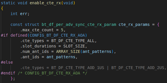
    Every second i get a batch of 5 CTE signals. (probably because in the code i have .max_cte_count = 5)
    The first one comes from a random channel and the other ones always come from channel 0.

    Is this normal?
    Should i discard the 1st signal? or the other 4? or none?

    Update: the 5 signals look the same

  • Not sure what this is, have you changed anything else in the sample than the number of antennas?

  • I used the zephyr connectionless locator example

    I changed the antenna switch pattern and the cte_recv_cb function to print the data the way i wanted.
    I changed the default slot_duration from 2us to 1us and that is it

    static void cte_recv_cb(struct bt_le_per_adv_sync *sync,
    			struct bt_df_per_adv_sync_iq_samples_report const *report)
    {
    	printk("CTE, samples, %d, channel_idx, %d, antennas, %d, ", report->sample_count, report->chan_idx, sizeof(ant_patterns)/sizeof(ant_patterns[0]));
    	for (int idx = 0; idx < report->sample_count; idx++) {
            printk("%d, %d, ", report->sample[idx].i, report->sample[idx].q);
        }
    	printk("\n");
    
        k_msleep(10);
    }

    #define ANT_1  0x5
    #define ANT_2  0x6
    #define ANT_3  0x4
    #define ANT_4  0x9
    #define ANT_5  0xA
    #define ANT_6  0x8
    #define ANT_7  0xD
    #define ANT_8  0xE
    #define ANT_9  0xC
    #define ANT_10 0x1
    #define ANT_11 0x2
    #define ANT_12 0x0
    static const uint8_t ant_patterns[] = { ANT_7, ANT_8, ANT_9 };

    I noticed this parameter .max_cte_count = 5. (i did not touch it here is the original sample code)
    It determines the number of CTEs i get per batch (but they are all the same)
    I dont understand the purpose though


    UPDATE:
    apparently i can set max_cte_count to 0 to receive CTE continuously and if i do so, i still get 5 CTEs
    so i went to the beacon code and i found this parameter

    /* Number of CTE send in single periodic advertising train */
    #define PER_ADV_EVENT_CTE_COUNT 5

    so my beacon sends 5 CTEs in a row
    for some reason the 1st one is sent on a random channel and the other on channel 0
    for some reason (unless i messed up my code) the signals are exactly the same

  • Also the signal during the reference period looks like an amplitude modulated signal and i cant see a clean phase.
    Is this due to undersampling or something ?
    i dont really follow what is going on with the demodulation.

     (this is a CTE without antenna switching)
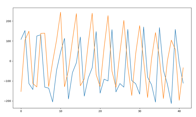
    also what frequency  should i expect for the signal?
    Here i have 16 samples per period.
    The samples are taken 2us apart.
    So i have a 32us period and 31.25kHz frequency

    My config:
    160us CTE signal with 1us slot duration
    (= 4us guard perdiod + 8us ref period + (74 x 2 x 1us)  sampling period)
    which gives me 8 + 74 samples

    There is a company called Navigine that published some opensource code for AoA and they use Minew hardware that is surely based on Nordic's PCA20054 antenna board.


    When you look at their signal it looks different from mine.
    On their reference period they have a normal signal that looks unmodulated and their sampling period looks like it is modulated in amplitude.
    Their reference period looks like my sampling period and their sampling period looks like my reference period.

    They also mention that they use  channels 37 38 and 39 which are the BLE advertising channels.
    But as you can see on my last reply, i get the signals on BLE  data channels like 0, 17, 28, 29, 31, 35, etc

Reply
  • Also the signal during the reference period looks like an amplitude modulated signal and i cant see a clean phase.
    Is this due to undersampling or something ?
    i dont really follow what is going on with the demodulation.

     (this is a CTE without antenna switching)

    also what frequency  should i expect for the signal?
    Here i have 16 samples per period.
    The samples are taken 2us apart.
    So i have a 32us period and 31.25kHz frequency

    My config:
    160us CTE signal with 1us slot duration
    (= 4us guard perdiod + 8us ref period + (74 x 2 x 1us)  sampling period)
    which gives me 8 + 74 samples

    There is a company called Navigine that published some opensource code for AoA and they use Minew hardware that is surely based on Nordic's PCA20054 antenna board.


    When you look at their signal it looks different from mine.
    On their reference period they have a normal signal that looks unmodulated and their sampling period looks like it is modulated in amplitude.
    Their reference period looks like my sampling period and their sampling period looks like my reference period.

    They also mention that they use  channels 37 38 and 39 which are the BLE advertising channels.
    But as you can see on my last reply, i get the signals on BLE  data channels like 0, 17, 28, 29, 31, 35, etc

Children
No Data
Related