nRF52832 current consumption in idle

This is my environment

  • IDE: VSC
  • SDK: NCS v2.2.0
  • nRF52832 on nRF52-DK
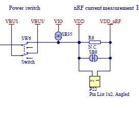
  • I've cut the SB9 link on the DK so I can measure the current only going to the nRF52832 IC, and am measuring the current using my CurrentRanger

This is what I am trying to do:

  1. Have my CPU go into a low power idle mode (should be < 2uA current consumption), then come out of this mode with a GPIO trigger
  2. Disable any peripherals prior to going into idle mode, then re-enable them on exit.  Note, I've disabled pretty much everything except UART0 in my overlay file

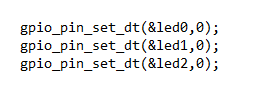
I've attached my test code to this ticket.  Nothing proprietary about this :-)

Here's what I am seeing:

  • in idle mode, I'm drawing about 200uA
  • pressing any of buttons 1, 2 or 3 seems to trigger the CPU out of idle and send my printk("Waking up from idle mode\n") statement to the Terminal, and toggle the appropriate LED.  However I'm not seeing the printk("Button x pressed\n") message for some reason.
  • If I press Button 2, then when it toggles the LED on, the current draw seems to drop down to something close to the 2uA I am expecting.  But this doesn't occur if I press Button 1 or 3, and if I press Button 2 a second time, so the LED goes off, the current goes up to ~ 200uA again

If I interpret the schematics for the nRF52-DK correctly, the only thing being powered via the "nRF Current Measurement" header P22 is the nRF52832 chip if SB9 is open circuit.

Can anyone see what I'm doing wrong?

Thanks and regards,

Mike

test_sample.zip

Parents
  • Hello Mike,

    200uA sounds like the current flowing through our internal pull resistors if the state of the pin is opposite of the pull config (e.g. pullup + pin set to low). Can I look at your set up how you measured the current using CurrentRanger? 

    Can you please explain this part of the code

    Did you mean to use same pin for 3 leds?

    Thanks.

    BR
    kazi

  • Hi Kazi,

    Looks like you were right!

    Changed my configuration for the LEDs to the following:

    ret = gpio_pin_configure_dt(&led1, GPIO_OUTPUT | \
    				 GPIO_OUTPUT_INIT_LOW |	\
    				 GPIO_OUTPUT_INIT_LOGICAL | \
    				 GPIO_OPEN_DRAIN);

    And I'm now seeing the sort of current in idle mode that I was expecting (well, as far as I can tell from my CurrentRanger - the current is jumping around a bit).  I might invest in a PPK 2 to get a better handle on what's truly going on.

    The gpio_pin_set_dt(&led0,0) code is there just there to turn the LEDs off at the start of my code.  I then toggle them in my button press callback.  As I understand it, I'm using three different LEDs in my code - led0, led1 and led2.  Am I missing something?

    Still can't work out why the printk("Button x pressed\n") messages aren't getting printed to the terminal in my callback though.  Are you able to see what I'm doing wrong?

    Regards,

    Mike

  • Hello Mike,

    Thanks for the explanation. 

    I can not see anything wrong in the code. Can you add the following configurations kconfig file and see if it works?

    CONFIG_CONSOLE=y
    CONFIG_UART_CONSOLE=y

Reply Children
No Data
Related