Level based control of GPIOTE


Hi,

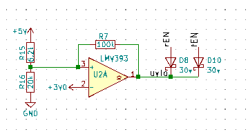
I have a comparator acting as a UVLO, it connects to a NRF52 pin with a pull-up. The comparator also pulls down two other circuits using a diode, which in turn are connected to other NRF52 pins using pull-ups. It works well.

I'd like if possible to remove the diodes and connecting the UVLO signal via GPIO Event through PPI and controlling the other two pins via GPIOTE SET and CLEAR.

What I can't determine from the datasheet is whether once the initial output of GPIOTE is set if PPI & GPIOTE are fully async to the clock in which case it would be like level control where they couldn't miss an event, or whether the clock is working to determine the event (like a D gate) in which case potentially the event could be missed.

It is only a small optimisation but one I thought I'd look at as I was contemplating moving the comparator to the built-in one.

Andrew

  • Hi,

    snoopy20 said:
    So, for some reason I thought GPIOTE PSEL had a null, it doesn't. That means I have to toggle from task to disable and vice versa sometimes, which potentially could race with the comparator output.

    So when I come to set a GPIOTE output I have to:

    a) ensure the comparator is level high
    b) set the gpiote pin high
    c) do the above atomically - the comparator can't go low between a and b.

    Your code disables the CFG_GPIOTE_POWERMANGER_FRONT /_REAR channels, ie. these will not be used by the GPIOTE module at all. Is this intended?

    If you want 'n' amount of GPIOTE TASKs to occur when EVENTS_DOWN is triggered, you should configure all your GPIOTE channels as TASK.

    In your PPI configuration, you seem to .FORK with the exact same TASK EP as originally set i CH[].TEP. 

    I highly suspect that you want the triggered GPIOTE OUT tasks to be reset in the .FORK operation? ie. if EVENTS_UP occurs, set "CFG_GPIOTE_POWERMANAGER_FRONT" and SET "CFG_GPIOTE_POWERMANAGER_REAR" ? Vice-versa on the EVENTS_DOWN ?


    snoopy20 said:
    However related to the original question I must ensure the GPIOTE pin always has the correct output. My understanding is if the GPIOTE is enabled as a task after the comparator is running then the PPI wont be picked up, because it's not propagating continuously by clock. I may be wrong with this and it is a fundamental question.

    It is clear to me that you're using the NRF_COMP peripheral, and not a external circuit, as I initially thought. Sorry for misunderstanding.

    GPIOTE is related to TASK and EVENT system. It can be tied towards an event or task occurring and performing a specific GPIO related task, like SET/CLR.

    Please note that PPI cannot perform a logical operation, like evaluating a if/else condition. PPI is quite simple in terms of what features can be done without CPU intervention.


    That being said, it looks like you want to set a given "bit pattern" on each event on a total of 3 GPIOs. Could you share the wanted state(s) based on each EVENTS_* that occurs?


    Kind regards,

    Håkon

  • Hi,

    Sorry that's an error (now corrected), the PPI event controls two pins, front and rear (I haven't tested this revised code yet, awaiting pcb arrival this week). The event actually controls three pins, but PPI only supports the single fork so I use two channels. Also one of the channels doesn't use the SET event.

    No, I am now using NRF_COMP. I managed to make a pin available, but whether it's comparator or gpiote input the query remains the same. :)

    All that matters is:

    a) ensure the comparator is level high
    b) set the gpiote pin high
    c) do the above atomically - the comparator can't go low between a and b.

    I occasionally need to override the GPIOTE output. At that point when I turn it back on it is not necessarily in sync with the comparator output. This is the problem with events rather than levels. Anyhow, it is a condition I must resolve.

    Simplied init:

      // gpiote
      NRF_GPIOTE->CONFIG[CFG_GPIOTE_POWERMANAGER_FRONT] = GPIOTE_CONFIG_MODE_Disabled << GPIOTE_CONFIG_MODE_Pos | CFG_PIN_POWERMANAGER_FRONT_ENABLE << GPIOTE_CONFIG_PSEL_Pos;
      
      // ppi
      NRF_PPI->CH[CFG_PPI_POWERMANAGER_UVLO_FRONTREAR_GOOD].EEP = (uint32_t) &NRF_COMP->EVENTS_UP;
      NRF_PPI->CH[CFG_PPI_POWERMANAGER_UVLO_FRONTREAR_GOOD].TEP = (uint32_t) &NRF_GPIOTE->TASKS_SET[CFG_GPIOTE_POWERMANAGER_FRONT];
      NRF_PPI->CH[CFG_PPI_POWERMANAGER_UVLO_FRONTREAR_BAD].EEP = (uint32_t) &NRF_COMP->EVENTS_DOWN;
      NRF_PPI->CH[CFG_PPI_POWERMANAGER_UVLO_FRONTREAR_BAD].TEP = (uint32_t) &NRF_GPIOTE->TASKS_CLR[CFG_GPIOTE_POWERMANAGER_FRONT];
     
      NRF_PPI->CHENSET = 1 << CFG_PPI_POWERMANAGER_UVLO_FRONTREAR_GOOD
        | 1 << CFG_PPI_POWERMANAGER_UVLO_FRONTREAR_BAD;
    
      // UVLO
      NRF_COMP->REFSEL = UVLO_REFERENCE << COMP_REFSEL_REFSEL_Pos;
      NRF_COMP->TH = UVLO_HYSTERESIS_UP << COMP_TH_THUP_Pos | UVLO_HYSTERESIS_DOWN << COMP_TH_THDOWN_Pos;
      NRF_COMP->PSEL = COMP_UVLO << COMP_PSEL_PSEL_Pos;
      NRF_COMP->ENABLE = COMP_ENABLE_ENABLE_Enabled << COMP_ENABLE_ENABLE_Pos;
    

    Imagine you want to override GPIOTE output, by toggling GPIOTE_CONFIG_MODE_[Disabled|Task], and when you choose task it must give the same output as the current comparator state.

    Perhaps calling COMP.SAMPLE will fire and propagate the correct event?...

    Andrew

  • I may have a solution, if I leave GPIOTE Task enabled but instead switch GPIO to be an input with a pull-down enabled...?

    edit: datasheet suggests not. infocenter.nordicsemi.com/index.jsp

  • I think I have it. The UVLO is triggered by the two downstream circuits controlled by these enable pins, and the circuits are bucks which turn off fast and turn on slower. With that in mind when I want to turn either on...

    1. turn both off using GPIOTE_CONFIG_MODE_Disabled
    2. the comparator will now be in high.
    3. Turn an output on using GPIOTE_CONFIG_MODE_Task and OUTINIT=high
    4. Turn on the other output if it were already enabled.

    Given the speed/delay of the buck(s) turning on the comparator event wont fire between steps 3 and 4 so all will be in sync.

  • Hi,


    snoopy20 said:
    1. turn both off using GPIOTE_CONFIG_MODE_Disabled

    This will disable GPIOTE channel, and not really do anything with the state of the GPIO itself.

    This is highly likely not the functionality you're after.

    snoopy20 said:
    I may have a solution, if I leave GPIOTE Task enabled but instead switch GPIO to be an input with a pull-down enabled...?

    No, but you can use more PPI channels to ensure that other GPIOTE OUT channels are set in your wanted state at that time.


    Can you share a diagram or similar on how you want your GPIOs to be set in each COMP state?


    Kind regards,

    Håkon

Related