Using RX pin of uart0 to exit System On Low Power mode

This is my environment

  • IDE: VSC
  • SDK: NCS v2.2.0
  • nRF52832 on nRF52-DK

This is what I am trying to do:

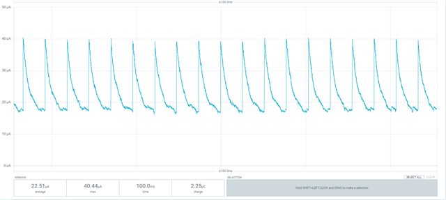
  1. Have my CPU go into a low power idle mode (should be < 2uA current consumption) whilst idle.  To get the lowest quiescent current, I'm effectively disabling the UART.
  2. Come out of this mode with negative going edge on the RX pin (p0.08).  The device that is transmitting will just send a dummy character to trigger the nRF52832 out of idle
  3. Enable the UART, send an "I'm active" message to the transmitting device over UART and then wait for data

I'm thinking the way I need to do this is to:

  1. Disable the UART using: pm_device_action_run(uart, PM_DEVICE_ACTION_SUSPEND);
  2. Set up P0.08 as: gpio_pin_configure_dt(&p0_08, GPIO_INPUT GPIO_ACTIVE_LOW);
  3. Configure a callback on P0.08: gpio_pin_interrupt_configure_dt(&p0_08,GPIO_INT_EDGE_TO_ACTIVE);
  4. In the callback, disable the interrupt configuration, and activate the UART: pm_device_action_run(uart, PM_DEVICE_ACTION_SUSPEND);

Has anyone done this in NCS and is the above approach the best way to go about this?  Or, better still, is it even going to work?

Best regards,

Mike

Parents
  • Hi,

    Yes, that looks like it should work fine to me. If you are seeing any errors when you use this implementation, or too high power draw, let me know and I'll do my best to help resolve the issue.

  • Hi Øivind,

    OK, I used this ticket for a bit of assistance:  NRF9160 Disable UART and RX pin into an interrupt pin 

    But essentially this is what I did:

    Added this to my overlay file

        custompins {
            compatible = "gpio-keys";
            rxwakeup: gpio_in_RX {
                gpios = <&gpio0 8 (GPIO_PULL_UP | GPIO_ACTIVE_LOW)>;
                label = "RX Wakeup";
            };
    
        };

    Had this to enable the wakeup function on an RX receive:

    int enable_rx_wakeup (void)
    {
    	int ret;
    
    	/* Configure the GPIO for RX wakeup*/
    	ret = gpio_pin_configure_dt(&rx_wakeup, GPIO_INPUT|GPIO_ACTIVE_LOW);
    	if (ret != 0) {
    		printk("Error configuring pin\n");
    		return ret;
    	}
    
    	ret = gpio_pin_interrupt_configure_dt(&rx_wakeup,GPIO_INT_EDGE_TO_ACTIVE);
    	if (ret != 0) {
    		printk("Error configuring interrupt\n");
    		return ret;
    	}
    
    	gpio_init_callback(&rx_wakeup_cb_data, device_rx_wakeup, BIT(rx_wakeup.pin));
    	ret = gpio_add_callback(rx_wakeup.port, &rx_wakeup_cb_data);
    	if (ret != 0) {
    		printk("Error adding callback\n");
    		return ret;
    	}
    
    	return 0;
    }

    And this as my callback function when the RX wakeup is triggered:

    void device_rx_wakeup(const struct device *dev, struct gpio_callback *cb, uint32_t pins)
    {
    	gpio_pin_toggle_dt(&led0);
    	button = 4;
    }

    Then had this in my main loop

    while (1) {
    		printk("Going into idle mode\n\n");
    		ret = enable_rx_wakeup();
    		if (ret !=0) {
    			printk("Error re-enabling RX wakeup\n");
    		}
    		pm_device_action_run(uart, PM_DEVICE_ACTION_SUSPEND);
    		k_cpu_idle();
    		ret = gpio_pin_interrupt_configure_dt(&rx_wakeup,GPIO_INT_DISABLE);
    		pm_device_action_run(uart, PM_DEVICE_ACTION_RESUME);
    		printk("Waking up from idle mode\n");
    		switch (button) {
    			case 1:
    			printk("Button 1 pressed\n");
    			break;
    
    			case 2:
    			printk("Button 2 pressed\n");
    			break;
    
    			case 3:
    			printk("Button 3 pressed\n");
    			break;
    
    			case 4:
    			printk("UART RX trigger\n");
    			break;
    
    			default :
    			break;
    
    		}
    	}

    That all seems to work, in that I will get the following messages on Terminal if I monitor the UART TX:

    ---- Sent utf8 encoded message: "q\n" ----
    Waking up from idle mode
    UART RX trigger
    Going into idle mode

    However, the current I am measuring with my PPK2 is higher than what I would expect.  I was expecting to see ~ 2uA in idle mode, and then the current jump up to a few mA when it gets triggered out of idle mode.  But instead, I see this:

    Its jumping around between 20uA and 40uA at about 200Hz.

    Any idea why the current isn't sitting steady at around 2uA as expected?

    Best regards,

    Mike

  • OK, I think I've sorted out my own issue.  Had the voltage of the PPK2 to the DUT set to 3.3V (that's what our custom hardware normally works off).  Setting it to 3.0V saw the current drop down to zero during idle, with a peak of about 2.5mA when I trigger it out of idle mode by sending a signal to the RX pin. Perhaps there is some sort of voltage clamping on the VDD rail if its above 3V? 

    The only outstanding issue is that the idle current seems unrealistically low though.  It is literally 0uA!  Does that seem right? I wouldn't expect it to be that low, even in System OFF mode.

    Best regards,

    Mike

Reply
  • OK, I think I've sorted out my own issue.  Had the voltage of the PPK2 to the DUT set to 3.3V (that's what our custom hardware normally works off).  Setting it to 3.0V saw the current drop down to zero during idle, with a peak of about 2.5mA when I trigger it out of idle mode by sending a signal to the RX pin. Perhaps there is some sort of voltage clamping on the VDD rail if its above 3V? 

    The only outstanding issue is that the idle current seems unrealistically low though.  It is literally 0uA!  Does that seem right? I wouldn't expect it to be that low, even in System OFF mode.

    Best regards,

    Mike

Children
No Data
Related