Why does the reference radio matching network have VSWR > 2?

Hi.  I've read an awesome answer by Martin Sivertsen on an old ticket, and I have a question about using a VNA to measure the complex impedance as seen into the radio matching network from the antenna side while it is in TX mode (2440 MHz non-modulated).
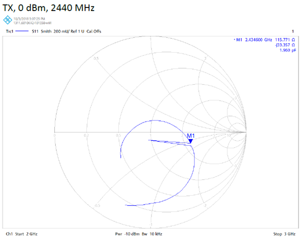
I measured the nRF52810 (with the recommended reference radio matching network) on outputs ranging from -40 dBm to -12 dBm and projected for +0 dBm a VSWR of about 2.4. Also, on the old ticket, Martin presented a (hopefully equivalent) measurement for the nRF52833 transmitting at +0 dBm where VSWR = 2.5 (from Smith chart 115.771 - j33.357 Ω).
Given that I would have expected better impedance matching (< 2.0), my question is: 
Is there a reason for the reference radio matching networks to be so far from 50 + j0 Ω other than to prioritize harmonic filtering?

Am I missing something obvious?

Thank you very much!

Parents
  • When you measure into the matching network from the antenna side like this, you necessarily don't see 50 ohm. The PA is setup for max output power and lowest harmonics. This happens around 70 ohm as Martin say in the thread you link to. This is relevant for the 8 dBm transmitters (820, 833 and 840) as the current in the PA transistors are reduced a bit so the harmoncs becomes lower. Else, you should see close to 50 ohm here for best output power. Why you measure different from this, I don't know. Byr layout and components does matter. You may have to adjust to compensate for this. 

    In any case, always verify with a spectrum analyzer and measure output power and harmonics. 

    Most VNAs can handle an inout power of 30 dBm or 1W. So the TX power from the nRF device should be ok here. The ANT pin on the nRF device can handle >0 dBm. The VNA usually has a power of -10 dBm. So no attenuator should be needed. 

Reply
  • When you measure into the matching network from the antenna side like this, you necessarily don't see 50 ohm. The PA is setup for max output power and lowest harmonics. This happens around 70 ohm as Martin say in the thread you link to. This is relevant for the 8 dBm transmitters (820, 833 and 840) as the current in the PA transistors are reduced a bit so the harmoncs becomes lower. Else, you should see close to 50 ohm here for best output power. Why you measure different from this, I don't know. Byr layout and components does matter. You may have to adjust to compensate for this. 

    In any case, always verify with a spectrum analyzer and measure output power and harmonics. 

    Most VNAs can handle an inout power of 30 dBm or 1W. So the TX power from the nRF device should be ok here. The ANT pin on the nRF device can handle >0 dBm. The VNA usually has a power of -10 dBm. So no attenuator should be needed. 

Children
  • You recommended that I verify my harmonics with an SA. That's precisely how I got here. I was disappointed with my harmonic filtering and was characterizing the current radio matching network before I started making changes. I will probably try to maintain the values and swap in components with higher Q.

    Both you and Martin said that 70 Ω are expected. Don't you find it strange that Martin measured 115.771 - j33.357 Ω ?

    Martin's

    Your comments on VNAs power tolerance were appreciated, Ketiljo.

    Thanks!

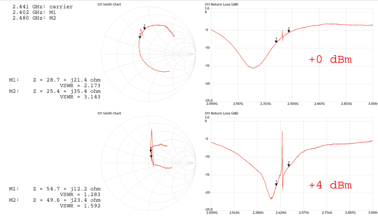
  • Just like you said, Ketiljo, my VNA indeed tolerates higher input powers. So I took new measurements.  At +0 dBm, as I predicted, the VSWR is still a bit high. But at +4 dBm, it is is surprisingly great, at about 1.4.

     
    I did not expect such a degree of variability in the impedance matching over differences in power outputs. Now I know better.

    Thanks!
Related