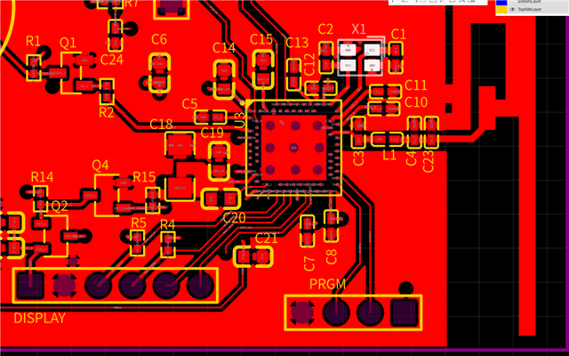
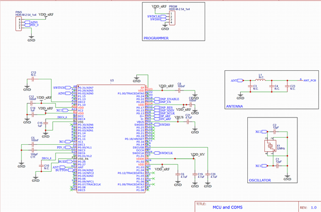
This is my first custom board with a microcontroller. Also my first time programming with SWD. Grateful for any help/suggestions :-).
Question: Can anyone identify a potential hardware issue that would prevent programming or connecting to the nRF52?


Situation: I am trying to flash an nRF52840 through the SWD pins, on a custom board I designed. The debugger cannot connect - "init mode failed (unable to connect to the target)". I can successfully connect to the st-link I am using and have connected to a nRF52840 on a DONGLE board.
Setup: I am using the following components.
NOTE: I successfully used this setup to connect to the nRF52840 DONGLE. Hence, I think it's a HW issue.
- STLINK-V3MINIE (STLINK-V3MINIE - STLINK-V3 compact in-circuit debugger and programmer for STM32 - STMicroelectronics)
- TVDD -> VDD
- GND -> GND
- CLK -> SWDCLK
- TMS ->SWDIO
- External bench power supplies 3V directly to VDD pin. VDDH pin is left floating
- OpenOCD through Windows PS.
- version:0.12.0
- PS command: openocd -f interface/stlink.cfg -c "transport select hla_swd" -f target/nrf52.cfg -c init -c "reset init"
- STSW-LINK009 Driver
- Windows 11
Parts:
- Supplier: JLCPCB, assembled with their components.
- nrf52 package: aQFN73
Additional Information:
- When powered through the USB (5V0), VDD is 1.8V.
- All other ICs seem to function normally.
- nRESET pin is floating
- The STLINK-V3MINIE is NOT able to write the APPROTECT bit
- Research indicates this bit is SET by default
- Could this prevent connection?
- The STLINK-V3 can only program between 3V and 3.6V and cannot supply power.
- I am powering VDD pin directly to solve this issue.
*The programmer header is on the bottom right side, top layer.
Gerber_PCB_Dodge_Clock.zipBOM_PCB_Dodge_Clock_2023-11-28.csv


