Setup:
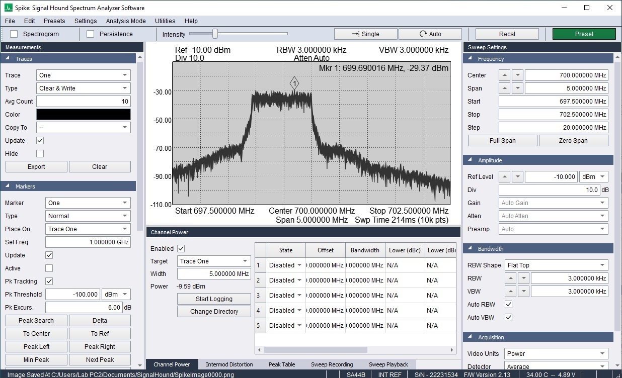
I am doing a conducted test with the nrf9160 connected directly to a Signal Hound SA44B spectrum analyzer.
I have a dc block and 30dB attenuators installed to protect the spectrum analyzer.
Pin 61 is using the same components as the nrf9160 Feather design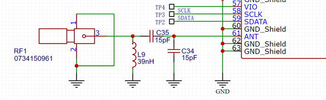
Test:
Command I'm using to test max power is:
AT%XRFTEST=1,1,12,7000,23,1,1,6,0,0,3,3,0
Command I'm using to test a lower power level is:
AT%XRFTEST=1,1,12,7000,10,1,1,6,0,0,3,3,0
For the max power test the nrf9160 is returning 276/16 = 17.25dBm
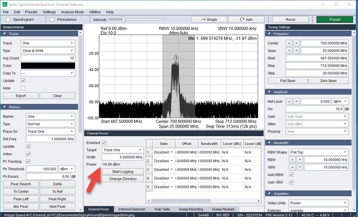
Here is my spectrum analyzer screenshot of the test measuring -19.39dBm
Questions:
1. Why isn't nrf9160 returning a transmit value for the max power 23dBm as expected by the command?
2. I have done several different tests with/without attenuators to try figure out why my spectrum analyzer is reading about 6dBm lower than the nrf9160 is telling me on B12. Why is my spectrum analyzer reading 6dBm lower than the nrf9160 response value? On some other bands it is even 10 to 20dBm difference.
2. I see the nrf9160DK is using different components and topology on pin 61 for the antenna so which reference design is the best one to follow?
3. We are sending a lot of systems to the fringe which is why I need max power so what is a good baseline test and ideal results so I can conclude this PCB is as good as the nrf9160 can be for fringe operation?
I would really appreciate some help to try better understand how I can maximize the performance of the nrf9160 for operation on the fringe.
Thank you.