External flash reading jesd216, "SFDP magic 000000 invalid"

Hi,

I make a customer board and used GD25Q80C as the external Flash IC (not MX25);

Read the sfdp bfp of Flash by jesd216 sample (zephyr \ samples \ drivers \ jesd216),But it failed and prompted "SFDP magic 000000 invalid";

However, when I replaced GD25Q80C with MX25R64, it was successful;

My configuration is as follows:

I basically haven't changed the configuration of samples, only the IO port has been modified;

Can you see what the problem is?

The specifications for this IC are as follows

&spi2 {
	compatible = "nordic,nrf-spi";
	status = "okay";
	cs-gpios = <&gpio0 15 GPIO_ACTIVE_LOW>;
	pinctrl-0 = <&spi2_default>;
	pinctrl-1 = <&spi2_sleep>;
	pinctrl-names = "default", "sleep";
	mx25r64: mx25r6435f@0  {
		compatible = "jedec,spi-nor";
		reg = <0>;
		spi-max-frequency = <8000000>;
		jedec-id = [c8 40 14];
		size = <8388608>;//67108864
		wp-gpios = <&gpio0 22 GPIO_ACTIVE_LOW>;
		hold-gpios = <&gpio0 24 GPIO_ACTIVE_LOW>;
	};
};

	spi2_default: spi2_default {
		group1 {
			psels = <NRF_PSEL(SPIM_SCK, 0, 17)>,//19
				<NRF_PSEL(SPIM_MOSI, 0, 20)>,//20
				<NRF_PSEL(SPIM_MISO, 0, 13)>;//21
		};
	};

	spi2_sleep: spi2_sleep {
		group1 {
			psels = <NRF_PSEL(SPIM_SCK, 0, 17)>,//19
				<NRF_PSEL(SPIM_MOSI, 0, 20)>,//20
				<NRF_PSEL(SPIM_MISO, 0, 13)>;//21
			low-power-enable;
		};
	};
	
/////prj
CONFIG_STDOUT_CONSOLE=y
CONFIG_FLASH=y
CONFIG_FLASH_JESD216_API=y

# Assume the standard SPI NOR flash driver.  If the device uses
# another driver add an override configuration in boards/.
CONFIG_SPI=y
CONFIG_SPI_NOR=y

CONFIG_UART_CONSOLE=y
CONFIG_CLOCK_CONTROL_NRF_K32SRC_RC=y
CONFIG_SOC_ENABLE_LFXO=n

Parents
  • Hi,other note:

    I use SPI_Flash example was used for debugging, and the results are as follows:

    Use MX25 for testing, if the following statement is not deleted, it will prompt "device not ready";

    	if (!device_is_ready(flash_dev)) {
    		printk("%s: device not ready.\n", flash_dev->name);
    		return 0;
    	}

    After shielding it, it can be read correctly:

    	//if (!device_is_ready(flash_dev)) {
    	//	printk("%s: device not ready.\n", flash_dev->name);
    	//	return 0;
    	//}

    However, After I switched to GD25 and blocked "device_isready", the read value was 00

    Perform test on single sector
    Test 1: Flash erase
    Flash erase succeeded!
    
    Test 2: Flash write
    Attempting to write 4 bytes
    Data read does not match data written!!
    0000f000 wrote 55 read 00 MISMATCH
    0000f001 wrote aa read 00 MISMATCH
    0000f002 wrote 66 read 00 MISMATCH
    0000f003 wrote 99 read 00 MISMATCH
    

    &spi2 {
    	compatible = "nordic,nrf-spim";
    	status = "okay";
    	cs-gpios = <&gpio0 15 GPIO_ACTIVE_LOW>;
    	pinctrl-0 = <&spi2_default>;
    	pinctrl-1 = <&spi2_sleep>;
    	pinctrl-names = "default", "sleep";
    	mx25r64: mx25r6435f@0  {
    		compatible = "jedec,spi-nor";
    		reg = <0>;
    		
    		spi-max-frequency = <12000000>;//8000000
    		jedec-id = [c8 40 14];
    		size = <8388608>;//67108864
    		has-dpd;
    		t-enter-dpd = <10000>;
    		t-exit-dpd = <35000>;
    
    		wp-gpios = <&gpio0 22 GPIO_ACTIVE_LOW>;
    		hold-gpios = <&gpio0 24 GPIO_ACTIVE_LOW>;
    	};
    };
    
    conf:
    CONFIG_NORDIC_QSPI_NOR=n
    
    CONFIG_SPI_NOR=y
    CONFIG_SPI=y

    I don't know how to get started, 

    When using GD25, I used an oscilloscope to grab the SO pin and found that it always kept a low level

  • Hi,

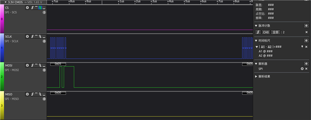
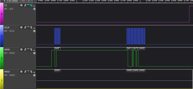
    I use a logic analyzer to monitor the command to send GD25, which is very strange: (I have blocked the erase function

    printf("\nTest 1: Flash erase\n");
    
    	/* Full flash erase if SPI_FLASH_TEST_REGION_OFFSET = 0 and
    	 * SPI_FLASH_SECTOR_SIZE = flash size
    	 */
    	//rc = flash_erase(flash_dev, SPI_COMMON_OFFSET,
    	//		 SPI_FLASH_SECTOR_SIZE);
    	//if (rc != 0) {
    	//	printf("Flash erase failed! %d\n", rc);
    	//} else {
    	//	printf("Flash erase succeeded!\n");
    	//}
    
    	printf("\nTest 2: Flash write\n");
    
    	printf("Attempting to write %zu bytes\n", len);
    	rc = flash_write(flash_dev, SPI_COMMON_OFFSET, expected, len);
    	if (rc != 0) {
    		printf("Flash write failed! %d\n", rc);
    		return;
    	}
    
    	memset(buf, 0, len);
    	rc = flash_read(flash_dev, SPI_COMMON_OFFSET, buf, len);
    	if (rc != 0) {
    		printf("Flash read failed! %d\n", rc);
    		return;
    	}
    
    	if (memcmp(expected, buf, len) == 0) {
    		printf("Data read matches data written. Good!!\n");
    	} 

    The results displayed by the oscilloscope:

    The first command is 0x05, followed by 0x00

    As shown in the above two pictures, it is all Write and Read; The written data is also different from the default value of the example

Reply
  • Hi,

    I use a logic analyzer to monitor the command to send GD25, which is very strange: (I have blocked the erase function

    printf("\nTest 1: Flash erase\n");
    
    	/* Full flash erase if SPI_FLASH_TEST_REGION_OFFSET = 0 and
    	 * SPI_FLASH_SECTOR_SIZE = flash size
    	 */
    	//rc = flash_erase(flash_dev, SPI_COMMON_OFFSET,
    	//		 SPI_FLASH_SECTOR_SIZE);
    	//if (rc != 0) {
    	//	printf("Flash erase failed! %d\n", rc);
    	//} else {
    	//	printf("Flash erase succeeded!\n");
    	//}
    
    	printf("\nTest 2: Flash write\n");
    
    	printf("Attempting to write %zu bytes\n", len);
    	rc = flash_write(flash_dev, SPI_COMMON_OFFSET, expected, len);
    	if (rc != 0) {
    		printf("Flash write failed! %d\n", rc);
    		return;
    	}
    
    	memset(buf, 0, len);
    	rc = flash_read(flash_dev, SPI_COMMON_OFFSET, buf, len);
    	if (rc != 0) {
    		printf("Flash read failed! %d\n", rc);
    		return;
    	}
    
    	if (memcmp(expected, buf, len) == 0) {
    		printf("Data read matches data written. Good!!\n");
    	} 

    The results displayed by the oscilloscope:

    The first command is 0x05, followed by 0x00

    As shown in the above two pictures, it is all Write and Read; The written data is also different from the default value of the example

Children
No Data
Related