External flash reading jesd216, "SFDP magic 000000 invalid"

Hi,

I make a customer board and used GD25Q80C as the external Flash IC (not MX25);

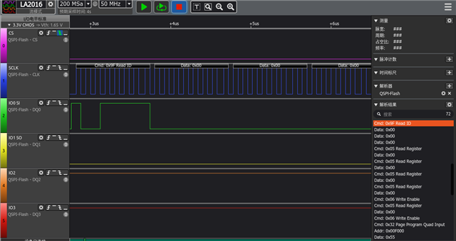
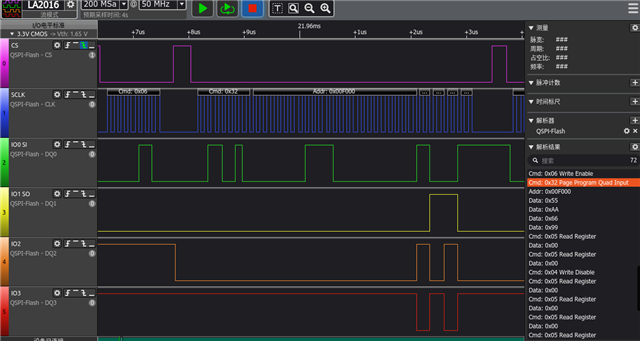
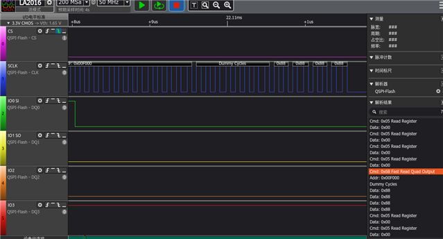
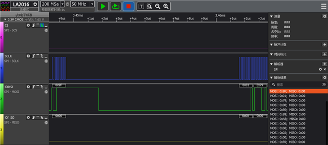
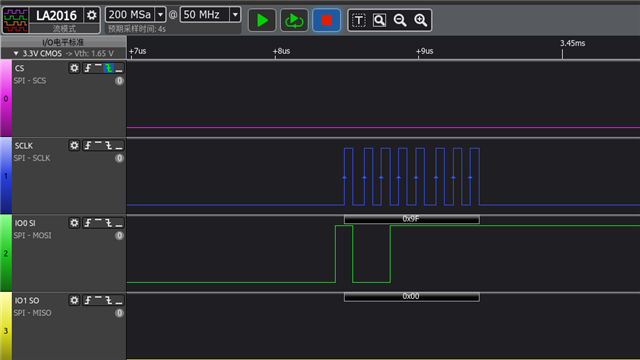
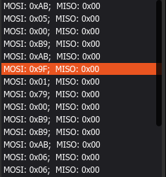
Read the sfdp bfp of Flash by jesd216 sample (zephyr \ samples \ drivers \ jesd216),But it failed and prompted "SFDP magic 000000 invalid";

However, when I replaced GD25Q80C with MX25R64, it was successful;

My configuration is as follows:

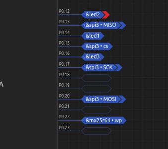
I basically haven't changed the configuration of samples, only the IO port has been modified;

Can you see what the problem is?

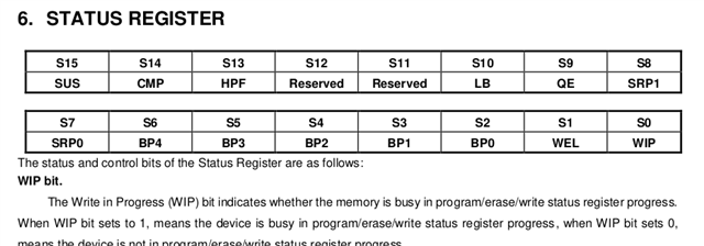
The specifications for this IC are as follows

&spi2 {
	compatible = "nordic,nrf-spi";
	status = "okay";
	cs-gpios = <&gpio0 15 GPIO_ACTIVE_LOW>;
	pinctrl-0 = <&spi2_default>;
	pinctrl-1 = <&spi2_sleep>;
	pinctrl-names = "default", "sleep";
	mx25r64: mx25r6435f@0  {
		compatible = "jedec,spi-nor";
		reg = <0>;
		spi-max-frequency = <8000000>;
		jedec-id = [c8 40 14];
		size = <8388608>;//67108864
		wp-gpios = <&gpio0 22 GPIO_ACTIVE_LOW>;
		hold-gpios = <&gpio0 24 GPIO_ACTIVE_LOW>;
	};
};

	spi2_default: spi2_default {
		group1 {
			psels = <NRF_PSEL(SPIM_SCK, 0, 17)>,//19
				<NRF_PSEL(SPIM_MOSI, 0, 20)>,//20
				<NRF_PSEL(SPIM_MISO, 0, 13)>;//21
		};
	};

	spi2_sleep: spi2_sleep {
		group1 {
			psels = <NRF_PSEL(SPIM_SCK, 0, 17)>,//19
				<NRF_PSEL(SPIM_MOSI, 0, 20)>,//20
				<NRF_PSEL(SPIM_MISO, 0, 13)>;//21
			low-power-enable;
		};
	};
	
/////prj
CONFIG_STDOUT_CONSOLE=y
CONFIG_FLASH=y
CONFIG_FLASH_JESD216_API=y

# Assume the standard SPI NOR flash driver.  If the device uses
# another driver add an override configuration in boards/.
CONFIG_SPI=y
CONFIG_SPI_NOR=y

CONFIG_UART_CONSOLE=y
CONFIG_CLOCK_CONTROL_NRF_K32SRC_RC=y
CONFIG_SOC_ENABLE_LFXO=n

Parents Reply Children
  • Hi, thank you for your reply;

    I have modified the jedec-id according to the specifications, but it still cannot be accessed through the device_ Is_ Ready;

    I will use device_ Is_ Ready to delete and capture QSPI communication, please help me see where the problem is?

    int main(void)
    {
    	//DT_NODELABEL(mx25r64)
    	const struct device *flash_dev = DEVICE_DT_GET(DT_NODELABEL(mx25r64));//DT_ALIAS(spi_flash0)
    
    	if (!device_is_ready(flash_dev)) {
    		printk("%s: device not ready.\n", flash_dev->name);
    		//return 0;
    	}
    
    	printf("\n%s SPI flash testing\n", flash_dev->name);
    	printf("==========================\n");
    
    	single_sector_test(flash_dev);
    	}
    	
    	&qspi {
    	status = "okay";
    	pinctrl-0 = <&qspi_default>;
    	pinctrl-1 = <&qspi_sleep>;
    	pinctrl-names = "default", "sleep";
    	
    	mx25r64: mx25r6435f@0 {
    		compatible = "nordic,qspi-nor";
    		reg = <0>;
    		writeoc = "pp4o";//pp4io
    		readoc = "read4o";//read4io
    		sck-frequency = <8000000>;
    		jedec-id = [c8 40 14];
    		sfdp-bfp = [
    			e5 20 f1 ff  ff ff ff 03  44 eb 08 6b  08 3b 04 bb
    			ee ff ff ff  ff ff 00 ff  ff ff 00 ff  0c 20 0f 52
    			10 d8 00 ff  23 72 f5 00  82 ed 04 cc  44 83 68 44
    			30 b0 30 b0  f7 c4 d5 5c  00 be 29 ff  f0 d0 ff ff
    		];
    		size = <67108864>;
    		has-dpd;
    		t-enter-dpd = <10000>;
    		t-exit-dpd = <35000>;
    		
    	};
    	
    };


    The ID read out is 000000

     Write 4Byte of data to address 0xF00

    Read out the data,But the data is incorrect

    This is the manual for GD25; Please help me, thank you。

    It seems like the Flash IC is unresponsive when reading data?

    dd

    DS-00091-GD25Q80C-Rev2.8.pdf

    d

  • Hi

    I can take a look at the specification and logic analyzer trace tomorrow, but first, can you confirm that you enable write/read permissions with the OP codes from the GD25 datasheet? The QSPI driver should do this by default but it seems like you only do regular SPI?

    Best regards,

    Simon

  • Hi, thank you for your reply.

    I am using the example "spi_flash"

    I have found that the status registers of MX25 and GD25 are different (the position of "QE BIT" is different), so GD25 cannot use QSPI to complete communication because "QE" Bit serves QSPI;

    Therefore, I modified the code to SPI and used SPI3, but the command 0x9F was unresponsive. I checked the characteristics of the GD25 manual through a logic analyzer and only found a strange place. I am not sure if this is the cause, as shown in the following figure:

    After sending command 9f, there was a delay of 12.12 microseconds before starting to read data from GD25;

    Compared to yesterday's QSPI, when in QSPI mode, its SCK is continuous; Why does SCK have a delay during SPI?

    0x9F:

    wait 12.12us ,SCK starts reading data,but MISO not response

    Other explanations:

    The frequency of SCK is 8.3MHz

    2. I enabled command 0xAB and after sending command 0xAB, CS was raised by 1ms; (See SPI3 settings)

    The following figure shows the command sent by MCU before sending command 9f:

    I have placed my settings below, please help me take a look:

    &spi3 {
    	compatible = "nordic,nrf-spim";
    	status = "okay";
    	cs-gpios = <&gpio0 15 GPIO_ACTIVE_LOW>;
    	
    	pinctrl-0 = <&spi3_default>;
    	pinctrl-1 = <&spi3_sleep>;
    
    	pinctrl-names = "default", "sleep";
    	mx25r64: mx25r6435f@0  {
    		compatible = "jedec,spi-nor";
    		status = "okay";
    		reg = <0>;
    
    		wp-gpios = <&gpio0 22 GPIO_ACTIVE_HIGH>;
    		hold-gpios = <&gpio0 24 GPIO_ACTIVE_HIGH>;
    
    		spi-max-frequency = <8000000>;//8000000
    		//sck-frequency = <8000000>;
    		jedec-id = [00 00 00];
    		size = <8388608>;//67108864
    
    		has-dpd;		
    		t-enter-dpd = <30000>;
    		t-exit-dpd = <30000>;		
    	};
    	
    };
    	spi3_default: spi3_default {
    		group1 {
    			psels = <NRF_PSEL(SPIM_SCK, 0, 17)>,
    				<NRF_PSEL(SPIM_MISO, 0, 13)>,
    				<NRF_PSEL(SPIM_MOSI, 0, 20)>;
    		};
    	};
    
    	spi3_sleep: spi3_sleep {
    		group1 {
    			psels = <NRF_PSEL(SPIM_SCK, 0, 17)>,
    				<NRF_PSEL(SPIM_MISO, 0, 13)>,
    				<NRF_PSEL(SPIM_MOSI, 0, 20)>;
    			low-power-enable;
    		};
    	};
    
    ////prj
    CONFIG_STDOUT_CONSOLE=y
    CONFIG_FLASH=y
    CONFIG_FLASH_JESD216_API=y
    
    # Assume the standard SPI NOR flash driver.  If the device uses
    # another driver add an override configuration in boards/.
    CONFIG_SPI=y
    CONFIG_SPI_NOR=y
    
    
    CONFIG_NORDIC_QSPI_NOR=y
    CONFIG_NFCT_PINS_AS_GPIOS=y 
    CONFIG_SPI_NOR_IDLE_IN_DPD=y
    
    CONFIG_UART_CONSOLE=y
    CONFIG_CLOCK_CONTROL_NRF_K32SRC_RC=y
    CONFIG_SOC_ENABLE_LFXO=n
    ///////
    int main(void)
    {
    	//DT_NODELABEL(mx25r64)
    	const struct device *flash_dev = DEVICE_DT_GET(DT_NODELABEL(mx25r64));//DT_ALIAS(spi_flash0)
    
    	if (!device_is_ready(flash_dev)) {
    		printk("%s: device not ready.\n", flash_dev->name);
    		//return 0;
    	}
    
    	printf("\n%s SPI flash testing\n", flash_dev->name);
    	printf("==========================\n");
    
    	single_sector_test(flash_dev);
    #if defined SPI_FLASH_MULTI_SECTOR_TEST
    	multi_sector_test(flash_dev);
    #endif
    	return 0;
    }
    

  • Also, can the value of the QE command be changed during QSPI mode? I found through the logic analyzer that the command 0x01 0x40 will be sent. Can this 0x40 be changed to the value I want? The following figure shows the location of QE for GD25:

    The QE Of MX25 is in the S6;

    The QE of GD25 is in the S9;

Related