LCD display shows unwanted characters

I'm working on a project using nRF52840 DK. I need to interface ublox neo6m GPS module, 2x16 ALCD, and an accelerometer module(ADXL345). LCD and accelerometer modules are interfaced using I2C and Neo 6m GPS module via UART. I use a power bank to supply all the modules including nRF52840 DK and all the other modules. After powering on the LCD will show Latitude and longitude values and  XYZ  axis values on the LCD And also notify these data to the mobile application via BLE. But the issue is that I'm getting unwanted characters displayed on the LCD after some time. I can't specifically say when the issue happens. It occurs sometimes very early and sometimes works better more time but eventually ends up in a glitch.  I tried some workaround to fix this like,

1. Powering up the GPS module separately.

2. Tried changing the jumpers connected to LCD.

 But it didn't work out. Could you please guide me on this what could be wrong here?

Parents
  • Hello,

    Could you try to disable the internal pullups for your I2C pins, and instead use external 4.7 k Ohm ones?

    Other than that I would recommend that you use a logic analyzer to scope the pins of both the I2C and the LCD, so that we can verify where in your project the root of the issue is. Do you have access to a logic analyzer?

    Best regards,
    Karl

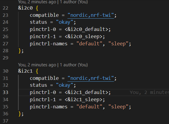
  • This is the i2c configurations in the overlay file im using,


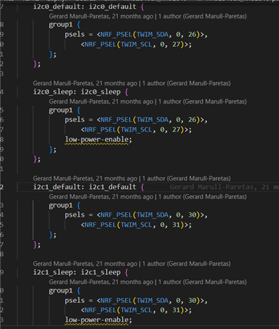
    And this is i2c pin configuration.

    Since i2c pin configuration shows nothing regarding pullups. I assume that it is disabled by default. Correct me if I'm wrong.

    And also this is the LCD module I'm using now.

    I was using the i2c0 channel initially with all the I2C support modules interfaced to same channel. I tried a workaround like using a separate channel to check if the interference is due to other slave devices. But still the issue persists im using i2c channel one now. I'm attaching the video of my findings here for your reference. Kindly guide me if anything is wrong in setup.

  • Hello,

    Thank you for the clarifications.

    The characters on the screen makes me suspect that there could be a mismatch in your configuration, or a hardware issue. Do you have access to an oscilloscope or logic analyzer, so that you may see what is being sent over the TWI? This would quickly help us pinpoint where the issue stems from.

    Best regards,
    Karl

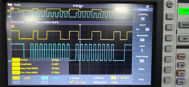
  • Hi I tried to probe the I2C pins of nRF52840 DK it is writing properly to LCD even though LCD glitch happening. attaching the video for your reference. Could it be hardware issue ?

  • Hello,

    It is hard to see exactly from the video of the oscilloscope, but at least the waveforms looks correct indeed, but it could still be a hardware issue with the LCD, yes.
    Was this scoped at the output of the nRF52?
    Do you have another LCD screen which you could perform a swap test with, i.e swap out the LCD shown here with the other LCD, to see if the other one behaves exactly the same?

    In general, is the unexpected symbols that show up always the same?

    It seems to me that it in the first part of the video functions as expected, and then in the second half it does not anymore - is there any difference to the test setup or program in the two instances?

    Best regards,
    Karl

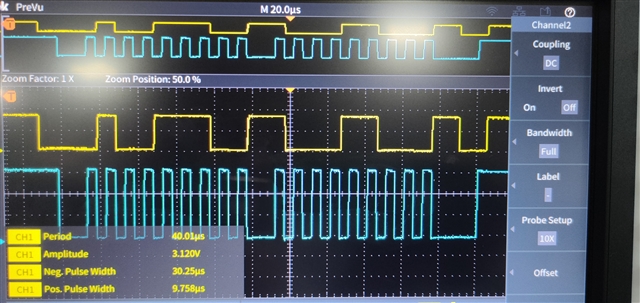
  • Yes in the first part of the video it was the expected one, and second part is with the. LCD glitch. I tried the swap test also but getting the same issue.Also tried to probe the pins after swapping the LCD. I think I2C com is fine. Properly writing data to LCD. Attaching the images before and after LCD glitches

Reply Children
  • Hello,

    Thank you for sharing this additional information as well.

    The flanks/characteristics for the communication looks correct in the shared screenshots, yes.
    The last thing we should check in this regard is that the written symbols actually
    You could do this by either going through the code to see that there are no chance these symbols could be the result of a memory shift, or similar, or to check this by exporting the trace from the logic analyzer/oscilloscope and verifying what is written this way.

    Have you reached out to the manufacturers of the LCD to see if they have any comment?
    If the communication from the nrf is verified to be correct then I am not sure exactly what our next step should be.
    Are you using an official driver for this LCD, or have you made it yourself?
    Perhaps there is an incorrect setting or configuration in the I2C communication, or similar.

    Best regards,
    Karl

Related