How to set nRF52832 to do parallel input and output?

Nrf52832 I/O is from P0.00~P0.31, I want to use one of the I/O to do parallel input and output, how to set? For example, with P0.02~P0.17, these 16 I/O ports make a 16-bit input parallel port.

Another experiment was done today, if Bluetooth sends data (calling ble_nus_data_send function) timer240us into an interrupt is not accurate. If only the Bluetooth connection is successful and no data is sent, 40us is accurate. This is also a problem with other timers.Could you please help me find out what the reason is?

Please help resolve these problems, thanks!

  • If BLE is running, the CPU is switching between 32MHz RC clock and 32MHz XTAL clock. This generates jitter.

    You can switch the CPU to permanent using the XTAL clock. This will cost you 100uA more current.

    #include <zephyr/drivers/clock_control.h>
    #include <zephyr/drivers/clock_control/nrf_clock_control.h>
    static const struct device *const clock0 = DEVICE_DT_GET_ONE(nordic_nrf_clock);
    static void start_xtal32(void) {
    // run from XTAL clock
    (void) clock_control_on(clock0, CLOCK_CONTROL_NRF_SUBSYS_HF);
    }
  • Hello,

    ''Nrf52832 I/O is from P0.00~P0.31, I want to use one of the I/O to do parallel input and output, how to set? For example, with P0.02~P0.17, these 16 I/O ports make a 16-bit input parallel port.''

    Could you please try to explain a bit detail what you're trying to achieve? For example: interface in more detail; is there a clock pin somewhere, and is that controlled from the nRF52 or somewhere else?

    You could configure 16 pins as input pins and receive 16 bits simultaneously, however the problem is, you have to implement different protocols with minimal or no hardware changes since we do not have any dedicated peripheral for this. 

    The NRF_GPIO->IN register allows you to read all 32 bits in parallel, and if you only care about a subset of the pins you can mask them out. 

    We have 8 GPIOTE channels on nRF52832. So, you can e.g. change state of these GPIO pins at the same time using PPI.

    Thanks.

    BR

    Kazi

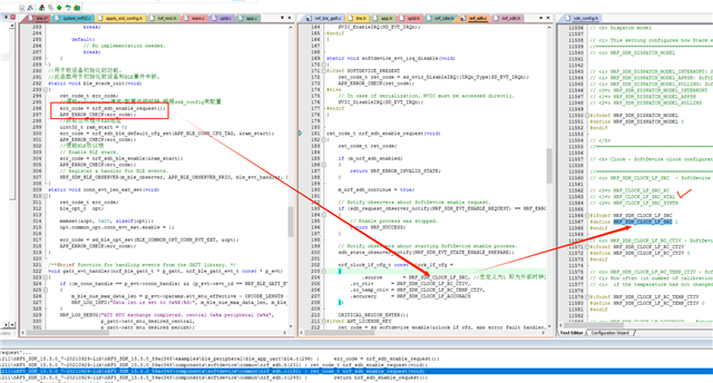
  • Thanks! But after I tried it, I found that It doesn't seem to be in the sdk package:

    #include <zephyr/drivers/clock_control.h>
    #include <zephyr/drivers/clock_control/nrf_clock_control.h>

    This is the XTAL clock, right? The previous program was already this clock.

  • The LF clock is 32KHz. You want the HF clock, I assume.

  • Ok, I see what you mean. We have also made a similar version, but there are a few questions that need to be answered by you.

    1, We now do all the input/output switching of these 16 pins in the GPIO interrupt. Another pin is controlled with PPI timing, and the level of this pin changes before starting the next round of communication, and 16 pins will be used.

    This 16-bit pin we have, we need to switch the input/output mode every time we communicate. Output first, and then switch to input after a GPIO interrupt. So these 16-digit pins can't be controlled with PPI?

    2,Could you please reply whether the response time of each interrupt will be affected when Bluetooth is sent? We can make other arrangements. Because we found that when Bluetooth is sent, it should not only affect the timer, for example, the GPIO interrupt is not so real-time, so this affects the interaction time between us and other chips, and affects the frequency of our acquisition chip.

Related