I have V2.5.0 asset_tracker_v2 running on a nrf9160DK board. I need to add I2C capability. I tried copying the code from the i2c_api example. I added "CONFIG_I2C=y" to prj.conf. I added the following to the overlay file:
/ {
aliases {
i2c-0 = &i2c0;
};
};
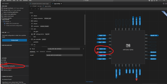
I get the following error when I try to compile the asset_tracker_v2. I have tried changing to i2c-1,i2c-2 and I still get the same error. what am I doing wrong? How do I add I2C capability to asset_tracker_v2 and what pins are the I2C signals (SCL/SDA) available?
In file included from C:/Nordic1/v2.5.0/zephyr/include/zephyr/toolchain.h:50,
from C:/Nordic1/v2.5.0/zephyr/include/zephyr/kernel_includes.h:19,
from C:/Nordic1/v2.5.0/zephyr/include/zephyr/kernel.h:17,
from C:/Nordic1/v2.5.0/zephyr/soc/arm/nordic_nrf/validate_enabled_instances.c:7:
C:/Nordic1/v2.5.0/zephyr/include/zephyr/toolchain/gcc.h:81:36: error: static assertion failed: "Only one of the following peripherals can be enabled: SPI2, SPIM2, SPIS2, TWI2, TWIM2, TWIS2, UARTE2. Check nodes with status \"okay\" in zephyr.dts."
81 | #define BUILD_ASSERT(EXPR, MSG...) _Static_assert(EXPR, "" MSG)
| ^~~~~~~~~~~~~~
C:/Nordic1/v2.5.0/zephyr/soc/arm/nordic_nrf/validate_enabled_instances.c:51:1: note: in expansion of macro 'BUILD_ASSERT'
51 | BUILD_ASSERT(CHECK(2), MSG(2));
| ^~~~~~~~~~~~
[119/466] Building C object zephyr/CMakeFiles/zephyr.dir/subsys/logging/log_core.c.obj
ninja: build stopped: subcommand failed.
FATAL ERROR: command exited with status 1: 'C:\Nordic1\toolchains\c57af46cb7\opt\bin\cmake.EXE' --build 'C:\Nordic1\test_n160\asset_tracker_v2\build'
************zephyr.dts******************
aliases {
led0 = &led0;
led1 = &led1;
led2 = &led2;
led3 = &led3;
pwm-led0 = &pwm_led0;
sw0 = &button0;
sw1 = &button1;
sw2 = &button2;
sw3 = &button3;
bootloader-led0 = &led0;
mcuboot-button0 = &button0;
mcuboot-led0 = &led0;
watchdog0 = &wdt0;
spi-flash0 = &mx25r64;
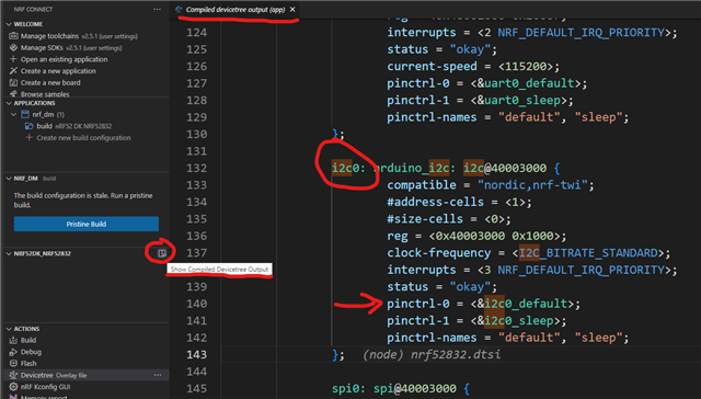
i2c-0 = &i2c0;
ext-flash = &mx25r64;
};
i2c0: i2c@8000 {
compatible = "nordic,nrf-twim";
#address-cells = < 0x1 >;
#size-cells = < 0x0 >;
reg = < 0x8000 0x1000 >;
clock-frequency = < 0x186a0 >;
interrupts = < 0x8 0x1 >;
status = "disabled";
};
i2c1: i2c@9000 {
compatible = "nordic,nrf-twim";
#address-cells = < 0x1 >;
#size-cells = < 0x0 >;
reg = < 0x9000 0x1000 >;
clock-frequency = < 0x186a0 >;
interrupts = < 0x9 0x1 >;
status = "disabled";
};
i2c2: arduino_i2c: i2c@a000 {
compatible = "nordic,nrf-twim";
#address-cells = < 0x1 >;
#size-cells = < 0x0 >;
reg = < 0xa000 0x1000 >;
clock-frequency = < 0x61a80 >;
interrupts = < 0xa 0x1 >;
status = "okay";
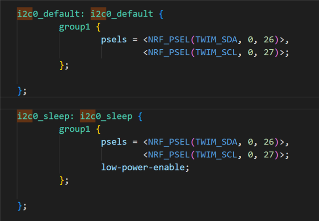
pinctrl-0 = < &i2c2_default >;
pinctrl-1 = < &i2c2_sleep >;
pinctrl-names = "default", "sleep";
pcal6408a: pcal6408a@20 {
compatible = "nxp,pcal6408a";
status = "disabled";
reg = < 0x20 >;
gpio-controller;
#gpio-cells = < 0x2 >;
ngpios = < 0x8 >;
int-gpios = < &gpio0 0x6 0x11 >;
};
};
i2c3: i2c@b000 {
compatible = "nordic,nrf-twim";
#address-cells = < 0x1 >;
#size-cells = < 0x0 >;
reg = < 0xb000 0x1000 >;
clock-frequency = < 0x186a0 >;
interrupts = < 0xb 0x1 >;
status = "disabled";
};