I2S: configuring clock details with Zephyr

Hello,

I have developed an NCS/Zephyr-based application that is able to stream out .WAV files over the I2S peripheral.

I have a dev board using a MAX98357A audio amplifier. This amplifier is able to interpret the I2S output from my nRF52840 and it plays my .WAV file normally out of a speaker.

Here is the I2S configuration I'm using to configure the Zephyr I2S driver:

    my_i2s_config.word_size = SAMPLE_BIT_WIDTH;			// 16
	my_i2s_config.channels = NUMBER_OF_CHANNELS;		// 1
	my_i2s_config.format = I2S_FMT_DATA_FORMAT_I2S;
	my_i2s_config.options = I2S_OPT_BIT_CLK_MASTER | I2S_OPT_FRAME_CLK_MASTER;
	my_i2s_config.frame_clk_freq = SAMPLE_FREQUENCY;	// 16000
	my_i2s_config.mem_slab = &mem_slab;
	my_i2s_config.block_size = BLOCK_SIZE;
	my_i2s_config.timeout = TIMEOUT;

With these settings, I am observing these I2S output clocks on my oscilloscope:
BCLK = 510kHz
LRCLK = 15.9kHz
BCLK to LRCLK Ratio: 32 

Now, I want to integrate a more advanced audio amplifier: the TI TAS2563. However, this audio amplifier does not support BCLK to LRCLK ratio of 32. It requires a minimum ratio of 64.

I still want my audio sampling frequency to be 16kHz, so I need to increase the BCLK speed up to ~1.024MHz.

I know that the previous NRFX drivers had registers for configuring the MCK_SETUP and MCK/LRCK ratio. I had a previous project (before NCS/Zephyr) where we used a MCK_SETUP value of NRF_I2S_MCK_32MDIV21 and a ratio value of NRF_I2S_RATIO_96X to get 16kHz streaming working. If I'm remembering the math correctly, this would give:

32MHz / 21 = 1.524MHz I2S peripheral clock
1.524MHz / 96 BCLKs/LRCLK = 15.9kHz LRCLK (close enough for 16kHz sampling)

Unfortunately, I do not see the options in the Zephyr driver to achieve this level of configuration over the I2S peripheral. 

Is there a way to configure the I2S peripheral from Zephyr such that I have a 16kHz LRCLK and a BCLK to LRCLK ratio of 64 or higher?

  • Hi 

    I suspect the issue here is that the ratio has no impact on the SCK output, AKA the BCLK, as can be seen from the SCK formula here

    Essentially the SCK clock is a simple multiple of the LRCK and the bitwidth, and is not affected by the MCK directly. 

    I did a quick test of this myself and confirmed that changing the ratio from 64 to 128 only affected MCK, not SCK or LRCK. 

    Have you tried to connect the MCK signal to the TAS2563 rather than the SCK, and see if this works fine? 

    I guess the question is when the TI device will sample the bits, since the output data from the nRF device will be changed according to SCK, not MCK. 

    Best regards
    Torbjørn

  • Hi  

    I tried this out today. I swapped the pins so that my SCK hardware is connected to the MCK output instead. This gives me a SCK rate of 1.53MHz with an LRCK of 16kHz, which matches the ratio I desire. The SCK output (now routed to my unused MCK pin) continues to run at 512kHz (ratio of 32x from the LRCK of 16kHz).

    However, you are also correct that the I2S peripheral is changing the SDOUT data according to the SCK rate, not the MCK rate. So this 'hack' technically gives me the SCK/LRCK ratio I desired, but now the data output does not align with the SCK, so it is still unusable.

    Are there any other techniques to directly set the SCK and LRCK speeds, rather than having the driver calculate them for me automatically?

    It would be great if both the LRCK and SCK could be directly set as a multiple of the I2S peripheral MCK value. Something like:

    MCK: 1.524MHz (set by mck_setup = NRF_I2S_MCK_32MDIV21, 32MHz oscillator / 21 = 1.524 MHz)
    BCK: 1.524MHz (1:1 BCK to LRCK ratio)
    LRCK: 15.875kHz (96 MCK cycles = 1 LRCK cycle, 1.524MHz/96 = 15.875kHz)

  • According to the formulas in the Infocenter documentation you linked to above, the two relevant formulas are:

    LRCK = MCK / CONFIG.RATIO

    SCK = 2 * LRCK * CONFIG.SWIDTH

    MCK is set by config.mck_setup = NRF_I2S_MCK_32MDIV21, giving MCK = 1.536MHz.

    config.ratio = NRF_I2S_RATIO_96X should give 16kHz (1.536MHz/16kHz = 96)

    SCK = 2 * LRCK * CONFIG.SWIDTH

    SCK = 2 * 16kHz * config.swidth

    Desired SCK: 1.024MHz, or 1.536MHz, or 2.048MHz

    1.024MHz = 2 * 16kHz * config.swidth
    config.swidth = 32

    Shouldn't this give me a BCK of 1.024MHz?

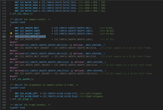
  • I can see that the nrf_i2s_swidth_t type, which is used for the config.swidth field, is defined at lines 176-197 in sdk/modules/hal/nordic/nrfx/hal/nrf_i2s.h:

    /** @brief I2S sample widths. */
    typedef enum
    {
        NRF_I2S_SWIDTH_8BIT          = I2S_CONFIG_SWIDTH_SWIDTH_8Bit,      ///< 8 bit.
        NRF_I2S_SWIDTH_16BIT         = I2S_CONFIG_SWIDTH_SWIDTH_16Bit,     ///< 16 bit.
        NRF_I2S_SWIDTH_24BIT         = I2S_CONFIG_SWIDTH_SWIDTH_24Bit,     ///< 24 bit.
    #if NRF_I2S_HAS_SWIDTH_32BIT
        NRF_I2S_SWIDTH_32BIT         = I2S_CONFIG_SWIDTH_SWIDTH_32Bit,     ///< 32 bit.
    #endif
    #if defined(I2S_CONFIG_SWIDTH_SWIDTH_8BitIn16) || defined(__NRFX_DOXYGEN__)
        NRF_I2S_SWIDTH_8BIT_IN16BIT  = I2S_CONFIG_SWIDTH_SWIDTH_8BitIn16,  ///< 8 bit sample in a 16-bit half-frame.
    #endif
    #if defined(I2S_CONFIG_SWIDTH_SWIDTH_8BitIn32) || defined(__NRFX_DOXYGEN__)
        NRF_I2S_SWIDTH_8BIT_IN32BIT  = I2S_CONFIG_SWIDTH_SWIDTH_8BitIn32,  ///< 8 bit sample in a 32-bit half-frame.
    #endif
    #if defined(I2S_CONFIG_SWIDTH_SWIDTH_16BitIn32) || defined(__NRFX_DOXYGEN__)
        NRF_I2S_SWIDTH_16BIT_IN32BIT = I2S_CONFIG_SWIDTH_SWIDTH_16BitIn32, ///< 16 bit sample in a 32-bit half-frame.
    #endif
    #if defined(I2S_CONFIG_SWIDTH_SWIDTH_24BitIn32) || defined(__NRFX_DOXYGEN__)
        NRF_I2S_SWIDTH_24BIT_IN32BIT = I2S_CONFIG_SWIDTH_SWIDTH_24BitIn32, ///< 24 bit sample in a 32-bit half-frame.
    #endif
    } nrf_i2s_swidth_t;

    However, when I try to use NRF_I2S_SWIDTH_32BIT or I2S_CONFIG_SWIDTH_SWIDTH_16BitIn32, I get errors that these values are not defined. Which makes sense, they are behind an #if defined block. These values are also ghosted out in the vs code editor, reinforcing that they are not defined in the current build:

    I tried defining NRF_I2S_HAS_SWIDTH_32BIT and I2S_CONFIG_SWIDTH_SWIDTH_16BitIn32 in my application, hoping to enable these 32 bit sample width options:

    #define NRF_I2S_HAS_SWIDTH_32BIT 1
    #define I2S_CONFIG_SWIDTH_SWIDTH_32Bit 1

    However, this did not appear to work. The 32 bit sample width options remain disabled.

    What do I need to do to enable the 32 bit sample width options?

  • I am noticing that despite my best efforts, I cannot seem to get an SCK/LRCK ratio of 64. I can get a ratio of 32, and I can get 48, but not 64.

    I can't help but wonder if this is related to the sample widths only showing support for 8, 16, and 24 bits.

    Given the formula SCK = 2 * LRCK * CONFIG.SWIDTH, it makes some sense to me that the max SCK/LRCK ratio I can get is 48, when the max SWIDTH I can support is 24 bits (2*24 = 48, and the LRCK cancels out).

    This makes me increasingly suspicious that the key to hitting my desired clock settings is enabling support for 32 bit sample widths for the I2S peripheral.

    What do I need to do to enable the 32 bit sample width options in the I2S driver?

Related