NRF52832 Pull-up / Pull-down Resistance

Is there a way to measure pull-up / pull-down resistance within firmware? Is it stored in some table?

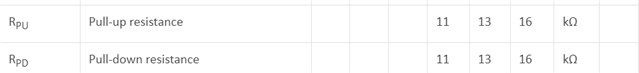
Additionally, do all the pull-up and pull-down resistors on a given chip have the same resistance? What is the distribution of the resistances from 11 to 16k like?

Thanks,

Aman

  • I should specify - I am referring to the GPIO pull-up and pull-down

  • Hello,

    There is no way to measure pull-up / pull-down resistance within firmware.

    They typical value of the pull up and pull-down resistances are in between 11 to 16. Mostly 13K (https://infocenter.nordicsemi.com/topic/ps_nrf52833/gpio.html?cp=5_1_0_5_7_2_0#unique_1378963434).

  • Yes there is :-)

    A PPK-II or other current meter will be required. The trick is to know that port pin pull-up and pull-down resistors are applied regardless of the port pin setting (documentation is wrong), which means that the pull-up can be measured by driving the port pin low and the pull-down by driving the port pin high. The internal driver FETs are equivalent to resistors (RDSon) and so best to use H0H1 as the FET resistance is lower than the S0S1 FET resistance; since this resistance is in series with the pull-up or pull-down resistor, and the H0H1 resistance is low enough to ignore.

    All  32 pins driven together give a mean value of 14k approx. Individual port pin measurements show that the pin-to-pin variation on each nRF52 is very small.

    // Here are my measurement results, which prove the pullup/pull-down resistor is connected to the pin regardless
    // of the input setting. nRF52832, 32MHz crystal, no 32kHz crystal, no Reset pin, SoftDevice loaded but not
    // enabled, no peripherals enabled, idle. Power CR2032 coin cell, no ground other than PPK-2, no J-Link.
    //
    // This first table is default port settings after a reset, no changes:
    //
    // PPK-2  Meter  Conditions
    // ====== ====== ==========
    // 1.66uA 2.971V with errata workarounds, no i/o
    // 1.51uA 2.985V   no errata workarounds, no i/o
    //
    // This Next table is port settings made after a reset, all 32 port pins identical, nothing connected to any of
    // the 32 port pins, no errata applied:
    //
    // PPK-2  Meter   Direction    Input            Pullup         Drive Level      Sense Level    Output
    // ====== ======  ==========   ==============   ============   ==============   ============== ===========
    //
    // 1.49uA 2.989V (PIN_OUTPUT | PIN_DISCONNECT | PIN_PULLNONE | PIN_DRIVE_S0S1 | PIN_SENSE_OFF) Driven Low
    // 1.49uA 2.999V (PIN_OUTPUT | PIN_DISCONNECT | PIN_PULLDOWN | PIN_DRIVE_S0S1 | PIN_SENSE_OFF) Driven Low
    // 6.47mA 2.894V (PIN_OUTPUT | PIN_DISCONNECT | PIN_PULLUP   | PIN_DRIVE_S0S1 | PIN_SENSE_OFF) Driven Low
    // 6.47mA 2.889V (PIN_OUTPUT | PIN_CONNECT    | PIN_PULLUP   | PIN_DRIVE_S0S1 | PIN_SENSE_OFF) Driven Low
    //
    // 1.51uA 2.959V (PIN_OUTPUT | PIN_DISCONNECT | PIN_PULLNONE | PIN_DRIVE_S0S1 | PIN_SENSE_OFF) Driven High
    // 6.42mA 2.877V (PIN_OUTPUT | PIN_DISCONNECT | PIN_PULLDOWN | PIN_DRIVE_S0S1 | PIN_SENSE_OFF) Driven High
    // 1.53uA 2.938V (PIN_OUTPUT | PIN_DISCONNECT | PIN_PULLUP   | PIN_DRIVE_S0S1 | PIN_SENSE_OFF) Driven High
    //
    //
    // This shows setting a port pin into active low output driven low is as good as leaving a pin floating
    // when unused, with the added benefit that there is no possibility of port feedthrough if a floating pin
    // drifts through the threshold.
    //
    // Looking at pull-up and pull down resistor values for the 32 pins:
    //
    //   (2.877Volts / 6.42mA) * 32 ==> 14.34K Ohm

    Conceptually the measurement code is trivial, insert before or after errata have been applied. Here's the example for testing the pull-up:

    #define NUMBER_PINS_TO_DRIVE 32
    static void TestPower(void)
    {
       // Set pins
       for (uint32_t i=0; i<NUMBER_PINS_TO_DRIVE; i++)
       {
            // Configuration      Direction    Input            Pullup       Drive Level      Sense Level
            // ===============    ==========   ==============   ==========   ==============   =============
            NRF_P0->PIN_CNF[i] = (PIN_OUTPUT | PIN_DISCONNECT | PIN_PULLUP | PIN_DRIVE_H0H1 | PIN_SENSE_OFF);
            NRF_P0->OUTCLR = (1UL << i);
       }
       // Sleep
       while (1)
           {
             __WFE();
             __NOP(); __NOP(); __NOP(); __NOP();
          }
    }
    

    To get the pin-pin variation, just drive each pin in turn rather than all 32 pins.

    Older posts: nrf52832-power-leakage

Related