I2C pull-up is behaving differently in development and custom board

Hello Nordic support team,

I am developing a custom board that includes 3 sensors on the I2C-bus (Analog Devices Max86150, Bosch BME280, Würth WSDN-ITDS) . I am using a nRF52840DK with external sensor evaluation boards. In the developmentkit there are no pull-ups on SDA and SCL active. So I am using external pull-ups (10k). I am supplying the sensors with 1,8V. And use the external pull-ups to pull the voltage on the I2C bus to the same voltage. As a compatible I am using TWIM. (With TWI the pull-ups just stay on...)

My issue now: On my custom board, when I flash it with the build config of my developmentkit the pull-ups are suddenly active (yes I know I should have a custom build config as well, but with the custom build config nothing really works). I have not configured it like this. When I turn them off in the pincontrol file, I am getting "Error occured for message 0". As far as I know this indicates a hardware issue. I looked at the bus in a scope and logic analyser and there is also no communication.

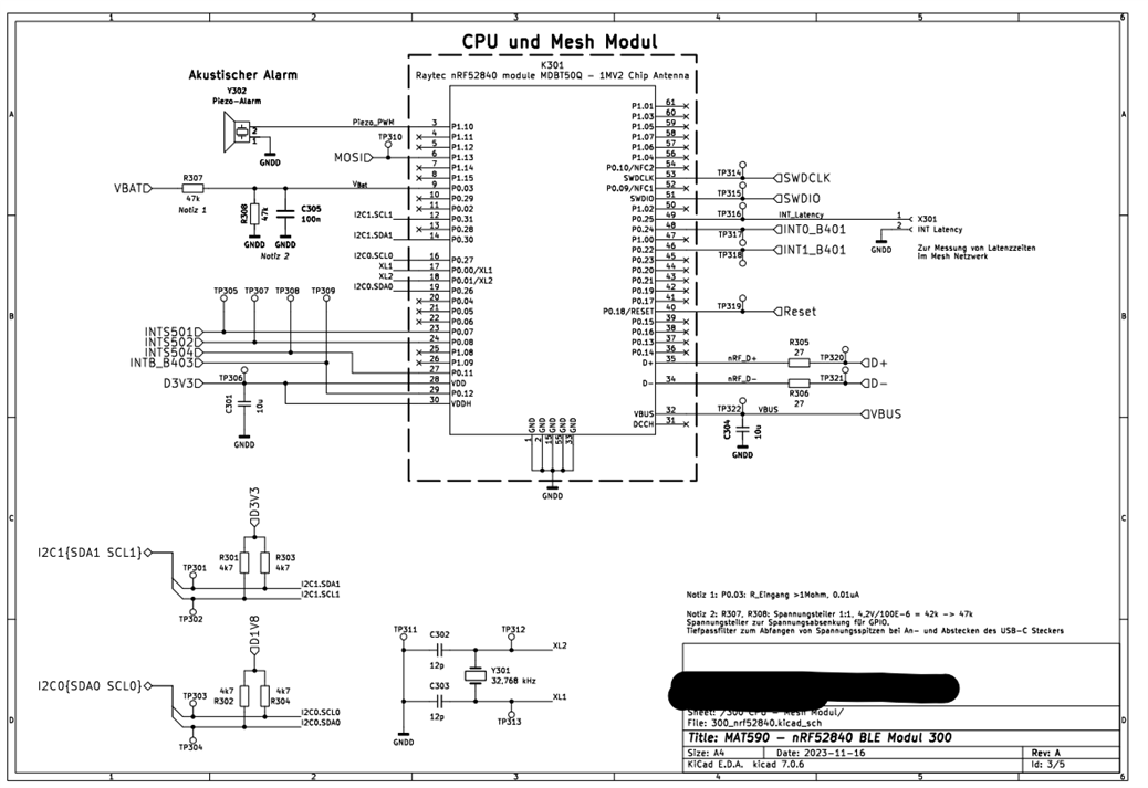
The custom board uses a Raytec nRF52840 module (MDBT50Q-1MV2 Chip Antenna). The module is supplied with 3,3V. External Pull-Ups pull to 1,8V. I have used 4,7k resistors in my custom board for the pull-ups.

Why are the pull-ups even active? When they are not in my developmentkit with the same build? And why does it work on the development kit and not with my custom board even if everything is the same?

Could it be that 1,8V is not enough for a good enough communication? But then why does this work in the DK?

Greetings

Niklas

  • Hello Niklas,

    I have started looking at your case. I will reply to you soon.

    Thanks.

    BR

    Kazi

  • Hello,

     ''I have not configured it like this. When I turn them off in the pincontrol file, I am getting "Error occured for message 0".''

    Did you mean that you turned the pull-up resistor off in your custom board?

    '' I am using a nRF52840DK with external sensor evaluation boards. In the development kit there are no pull-ups on SDA and SCL active. So I am using external pull-ups (10k).''

    So, there is pull up on the DK.

    However here you are asking about why pull ups are active?

    ''Why are the pull-ups even active? When they are not in my development kit with the same build? And why does it work on the development kit and not with my custom board even if everything is the same?'' 

    10k pull-up is not good enough for 400 kHz I2C transfer. You need around 5k Ohm pull up.

    Could you please share the schematic design of your custom board along with the setup pictures? 


  • Hi,

    okay please let me clarify: I have one build configuration for the nRF52840DK. When I flash my build to the DK I need to use external pull-ups for the I2C to work. The bus uses 1,8V since that is the Vcc for my sensors and the datasheets of the sensors state that there should not be much more voltage on any interface-pin that is much higher than 1,8V.

    When I now flash the same build onto my custom board it appears to be that the internal pull-ups switch on automatically when the I2C communication starts. So why are the resistors off in the DK and I need external resistors, but on my custom board the internal pull ups switch on?  The custom board is build like I set up my DK, also with external pull ups. I thought I needed those in order to build my custom hardware like I did with the DK.

    This is a part of the scematic of my custom board: (I2C0 is the troubled one)

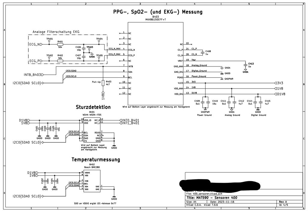
    I2C0 is routed to these sensors:

    I2C1 is routed to a display. I am having no trouble there in my custom board.

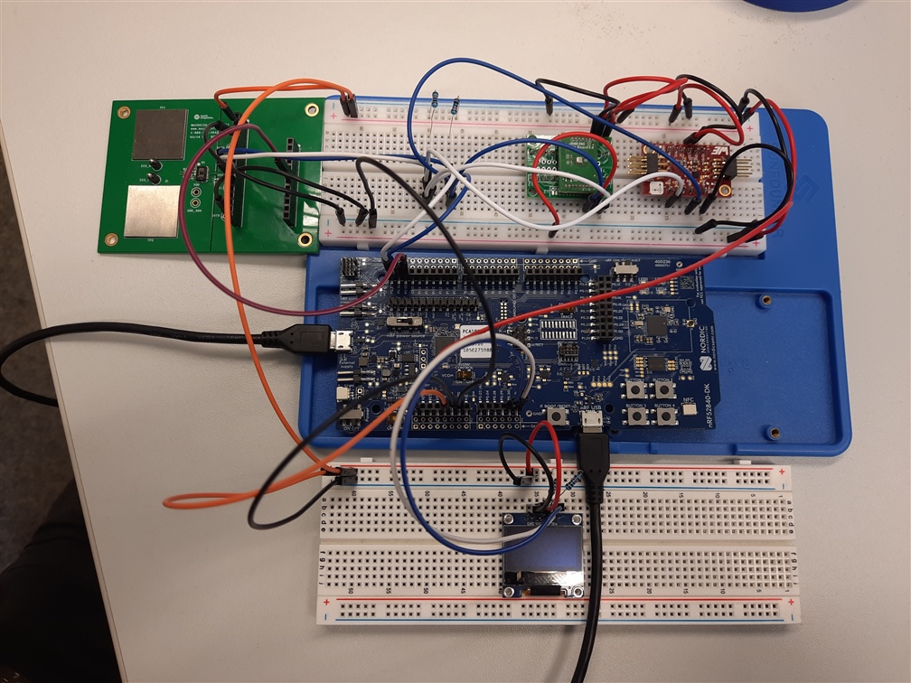
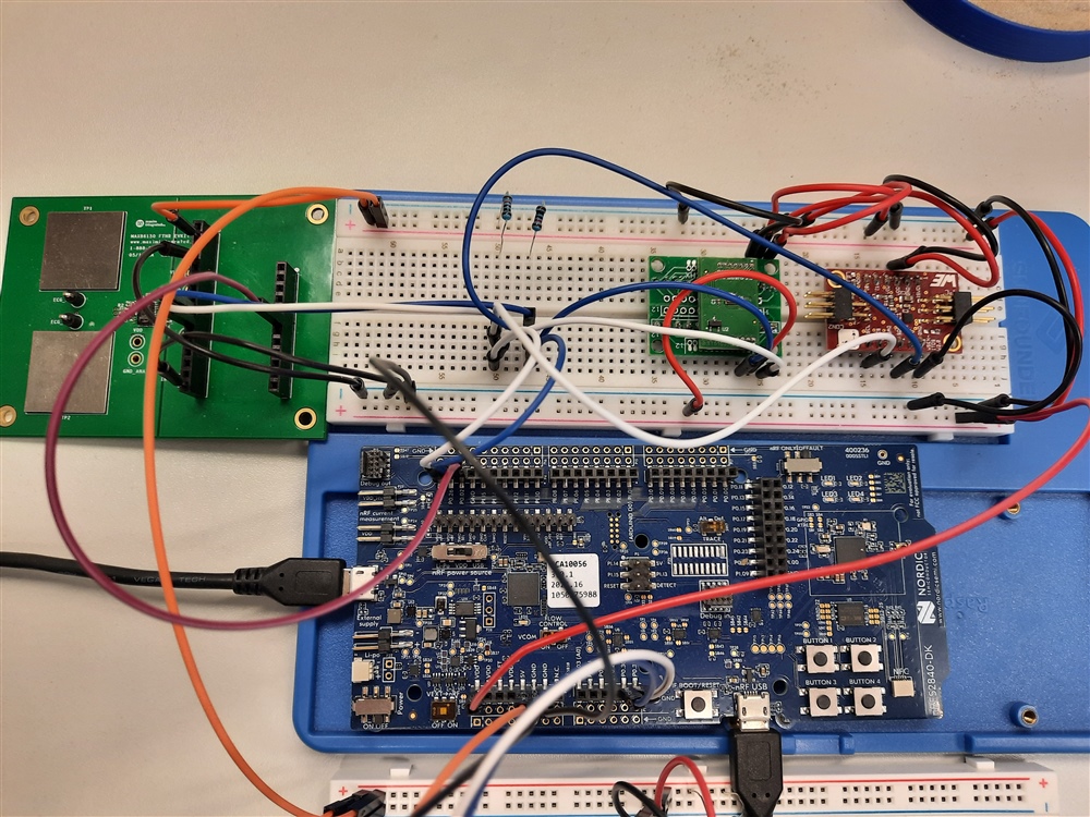
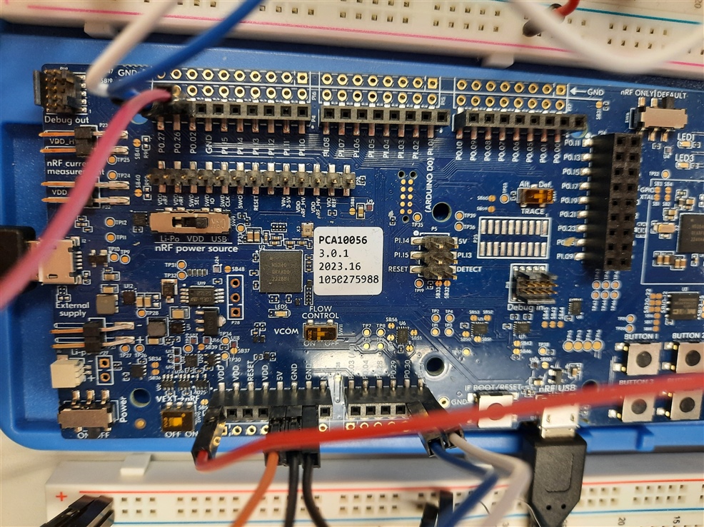
    I think with setup you mean developmentkit? So here are some pictures of the setup with the DK. I appologise for the jumper mess. With my DK everything works as I am expecting it too.

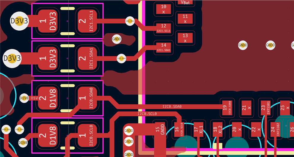
    In case this helps, here is a picture of the hardware design. What you are seeing is the down left corner of the raytec module and to the left the pull-up resistors for both I2C busses in use:

    Thank you very much. In case you need more information I am glad to provide it.

  • Hello,

    Is the pull up resistor enabled in the device tree of Dk? Could be that you need stronger pull-on DK than what internal can handle, compared to your custom board? You can enable pull-up on the I2C lines by adding the 'bias-pull-up' property to your i2c pin assignments in the device tree.

    There may be some differences in DTS if you use zephyr and have different build configs for DK and custom board? 

  • Hi,

    I tried using the internal pull-ups on my custom board, but then I am measuring 2,2V on the SDA and SCL lines. After reading all the datasheets of my sensors, that seems to be too high for them to handle. As I am supplying them with 1,8V they can't handle much more voltage on the interface pins.

    When I disable the pull-ups with "bias-disable" they still switch on when communications starts on the I2C bus.

    The only difference I noticed in the DT is that I have not marked the I2C pins in an arduino-header, like it is in the dts files of the nRF52840DK.

    I am trying now to use a level-transitioning IC from TI and I will hope that this will fix the issue on the hardware side.

    I will come back to you once I can test the new boards, since they are scheduled for delivery later this week.

Related