Hi,
I'm trying to get to know the nRF Connect SDK by starting with a simple project including two different boards. One of those is the nRF 52833DK, the other one is made by our own and has a nRF52832 chip on it. I've got GPIO's and PWM running, and also the ADC-inputs are showing the correct values. So far so good.
The idea is to generate a piece of code that can be used troughout all the boards we have or will design in the future. On these boards we often use the same hardware with a few additional components. For example; we allways use a light sensor named 'L458' and temperature sensor 'T100' or in some cases 'T189'. Ideally I would like to define name or label for each ADC-channel which I can use in the source code to determine which sensor is being used without any additional definitions.
General Idea
1. Loop trough each ADC-channel that is defined in the .dts file of the connected board periodically.
2. Based on the name of the ADC channel, convert the read-out voltage to something usefull, for example a temperature or light value.
#include <nordic/nrf52832_qfaa.dtsi>
#include <zephyr/dt-bindings/adc/adc.h>
#include "etd01_nrf52832-pinctrl.dtsi"
/ {
model = "ETD01 nRF52832";
compatible = "bever-innovations,etd01_nrf52832";
chosen {
zephyr,sram = &sram0;
zephyr,flash = &flash0;
zephyr,code-partition = &slot0_partition;
};
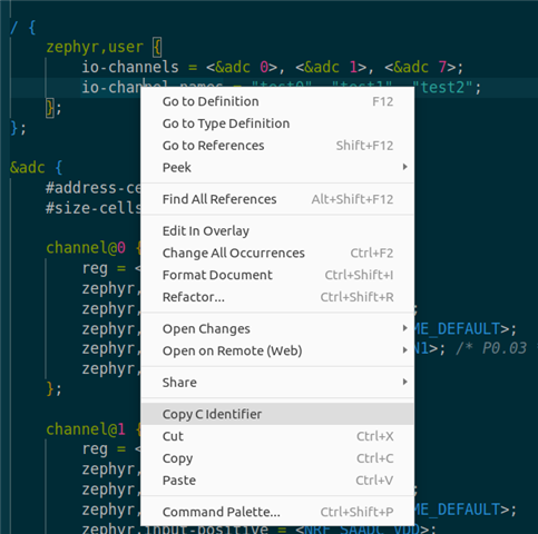
zephyr,user {
io-channels = <&adc 0>, <&adc 1>, <&adc 3>, <&adc 4>;
io-channel-names = "CURRENT_SENSE", "T100", "VDROP", "L458";
};
pwm {
compatible = "pwm-leds";
pwm_led_green: gr {
pwms = <&pwm0 0 PWM_KHZ(2) PWM_POLARITY_INVERTED>;
};
};
};
&flash0 {
/* snip */
};
&adc {
status = "okay";
#address-cells = <1>;
#size-cells = <0>;
channel@0 {
reg = <0>;
zephyr,gain = "ADC_GAIN_1_6"; // Keep input signal below ADC_REF_INTERNAL (0.6V) or ADC_REF_VDD_1_4
zephyr,reference = "ADC_REF_INTERNAL"; // Only ADC_REF_INTERNAL or ADC_REF_VDD_1_4
zephyr,acquisition-time = <ADC_ACQ_TIME_DEFAULT>;
zephyr,input-positive = <NRF_ADC_AIN0>;
zephyr,resolution = <10>;
};
channel@1 {
reg = <1>;
zephyr,gain = "ADC_GAIN_1_6"; // Keep input signal below ADC_REF_INTERNAL (0.6V) or ADC_REF_VDD_1_4
zephyr,reference = "ADC_REF_INTERNAL"; // Only ADC_REF_INTERNAL or ADC_REF_VDD_1_4
zephyr,acquisition-time = <ADC_ACQ_TIME_DEFAULT>;
zephyr,input-positive = <NRF_ADC_AIN1>;
zephyr,resolution = <10>;
};
channel@3 {
reg = <3>;
zephyr,gain = "ADC_GAIN_1_6"; // Keep input signal below ADC_REF_INTERNAL (0.6V) or ADC_REF_VDD_1_4
zephyr,reference = "ADC_REF_INTERNAL"; // Only ADC_REF_INTERNAL or ADC_REF_VDD_1_4
zephyr,acquisition-time = <ADC_ACQ_TIME_DEFAULT>;
zephyr,input-positive = <NRF_ADC_AIN3>;
zephyr,resolution = <10>;
};
channel@4 {
reg = <4>;
zephyr,gain = "ADC_GAIN_1_6"; // Keep input signal below ADC_REF_INTERNAL (0.6V) or ADC_REF_VDD_1_4
zephyr,reference = "ADC_REF_INTERNAL"; // Only ADC_REF_INTERNAL or ADC_REF_VDD_1_4
zephyr,acquisition-time = <ADC_ACQ_TIME_DEFAULT>;
zephyr,input-positive = <NRF_ADC_AIN4>;
zephyr,resolution = <10>;
};
};
&gpio0 {
status = "okay";
};
&gpiote {
status = "okay";
};
&pwm0 {
status = "okay";
pinctrl-0 = <&pwm0_default>;
pinctrl-names = "default";
};
The ADC example given by de nRF Connect SDK (C:\ncs\v2.5.1\zephyr\samples\drivers\adc) perfectly shows how to read-out all the ADC-channels that are defined in the board file. However, I'm struggeling how to connect the names given in the 'io-channel-names' to the defined adc-channels. Ideally I would like to give the channels in the .dts file a 'label' property, however this is not allowed. Also including a separate header file in the board with all sensor definitions doens't seem right, because the header file will be in the project folder and not in the boards directory.
Code so far (same as example)
while (1) {
		/* Read ADC */
		printk("ADC reading[%u]:\n", cnt++);
		for (size_t i = 0U; i < ARRAY_SIZE(adc_channels); i++) {
			int32_t val_mv;

			printk("- %s, channel %d: ",
			       adc_channels[i].dev->name,
			       adc_channels[i].channel_id);

			(void)adc_sequence_init_dt(&adc_channels[i], &sequence);

			volatile char name = adc_channel_names[i];

			err = adc_read(adc_channels[i].dev, &sequence);
			if (err < 0) {
				printk("Could not read (%d)\n", err);
				continue;
			}

			/*
			 * If using differential mode, the 16 bit value
			 * in the ADC sample buffer should be a signed 2's
			 * complement value.
			 */
			if (adc_channels[i].channel_cfg.differential) {
				val_mv = (int32_t)((int16_t)buf);
			} else {
				val_mv = (int32_t)buf;
			}

			printk("%"PRId32, val_mv);
			err = adc_raw_to_millivolts_dt(&adc_channels[i],
						       &val_mv);
			/* conversion to mV may not be supported, skip if not */
			if (err < 0) {
				printk(" (value in mV not available)\n");
			} else {
				printk(" = %"PRId32" mV\n", val_mv);
			}


			/*
			 * To-do
			 * Switch/case based on the name of the ADC-channel, convert val_mv to usable value
			 */
			switch(adc_channel[i].label)
			{
			    case 'T100':
			        OS.temp = convert_mv_to_temp(val_mv);
			        break;

			    default:
			        break;
			}
		}
	}
Can anyone give me a push in the right direction how to achieve this?
Thanks!