Hi,
I'm trying to move project from nrf52 SDK to new NCS.
I'm using custom board with nrf52832. There're some problems when working on i2c communication with LSM6DSL.
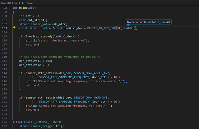
The project I'm testing is copied from "ncs\v2.5.1\zephyr\samples\sensor\lsm6dsl", so the main code and prj.conf are all same as usual.
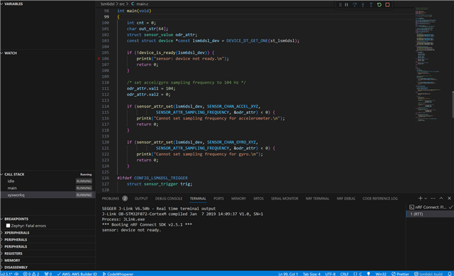
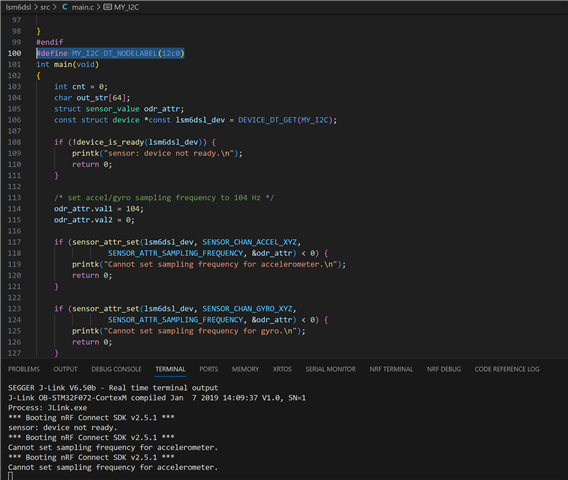
When I build and run the code to my board, just showed "sensor: device not ready."
Here are my other files currently, please help me to fix with it
for .dtsi file:
/*
 * Copyright (c) 2022 Nordic Semiconductor
 * SPDX-License-Identifier: Apache-2.0
 */

 &pinctrl {
	uart0_default: uart0_default {
		group1 {
			psels = <NRF_PSEL(UART_TX, 0, 6)>,
				<NRF_PSEL(UART_RX, 0, 8)>,
				<NRF_PSEL(UART_RTS, 0, 9)>,
				<NRF_PSEL(UART_CTS, 0, 7)>;
		};
	};

	uart0_sleep: uart0_sleep {
		group1 {
			psels = <NRF_PSEL(UART_TX, 0, 6)>,
				<NRF_PSEL(UART_RX, 0, 8)>,
				<NRF_PSEL(UART_RTS, 0, 9)>,
				<NRF_PSEL(UART_CTS, 0, 7)>;
			low-power-enable;
		};
	};

	i2c0_default: i2c0_default {
		group1 {
			psels = <NRF_PSEL(TWIM_SDA, 0, 11)>,
				<NRF_PSEL(TWIM_SCL, 0, 12)>;
			// bias-pull-up;
		};
	};

	i2c0_sleep: i2c0_sleep {
		group1 {
			psels = <NRF_PSEL(TWIM_SDA, 0, 11)>,
				<NRF_PSEL(TWIM_SCL, 0, 12)>;
			low-power-enable;
		};
	};

    pwm0_default: pwm0_default {
		group1 {
			psels = <NRF_PSEL(PWM_OUT0, 0, 3)>,
                <NRF_PSEL(PWM_OUT1, 0, 4)>,
                <NRF_PSEL(PWM_OUT2, 0, 5)>;
			nordic,invert;
		};
	};

	pwm0_sleep: pwm0_sleep {
		group1 {
			psels = <NRF_PSEL(PWM_OUT0, 0, 3)>,
                <NRF_PSEL(PWM_OUT1, 0, 4)>,
                <NRF_PSEL(PWM_OUT2, 0, 5)>;
			low-power-enable;
		};
	};

};
for dts file:
// Copyright (c) 2024 Nordic Semiconductor ASA
// SPDX-License-Identifier: Apache-2.0

/dts-v1/;
#include <nordic/nrf52832_qfaa.dtsi>
#include "custom_nrf52832-pinctrl.dtsi"

/ {
	model = "custom_nrf52832";
	compatible = "private,custom-nrf52832";

	chosen {
		zephyr,sram = &sram0;
		zephyr,flash = &flash0;
		zephyr,code-partition = &slot0_partition;
		zephyr,console = &uart0;
		zephyr,shell-uart = &uart0;
		zephyr,uart-mcumgr = &uart0;
	};

	leds {
		compatible = "gpio-leds";
		ledR: led_0 {
			gpios = <&gpio0 3 (GPIO_ACTIVE_LOW)>;
			label = "Red led R";
		};
		ledG: led_1 {
			gpios = <&gpio0 4 (GPIO_ACTIVE_LOW)>;
			label = "Green led G";
		};
		ledB: led_2 {
			gpios = <&gpio0 5 (GPIO_ACTIVE_LOW)>;
			label = "Blue led B";
		};
	};

	buttons {
		compatible = "gpio-keys";
		buttonC: button_0 {
			gpios = <&gpio0 27 0>;
			label = "Push button switch 0";
		};
	};

	pwmleds {
		compatible = "pwm-leds";
		pwm_ledR: pwm_led_0 {
			pwms = <&pwm0 0 PWM_MSEC(1) PWM_POLARITY_NORMAL>;
			label = "pwm led R";
		};
		pwm_ledG: pwm_led_1 {
			pwms = <&pwm0 1 PWM_MSEC(1) PWM_POLARITY_NORMAL>;
			label = "pwm led G";
		};
		pwm_ledB: pwm_led_2 {
			pwms = <&pwm0 2 PWM_MSEC(1) PWM_POLARITY_NORMAL>;
			label = "pwm led B";
		};
	};

	/* These aliases are provided for compatibility with samples */
	aliases {
		led0 = &ledR;
		led1 = &ledG;
		led2 = &ledB;
		pwm-led0 = &pwm_ledR;
		pwm-led1 = &pwm_ledG;
		pwm-led2 = &pwm_ledB;
		sw0 = &buttonC;
		bootloader-led0 = &ledR;
		mcuboot-button0 = &buttonC;
		mcuboot-led0 = &ledR;
		watchdog0 = &wdt0;
	};
};

&flash0 {
	partitions {
		compatible = "fixed-partitions";
		#address-cells = <1>;
		#size-cells = <1>;

		boot_partition: partition@0 {
			label = "mcuboot";
			reg = <0x0 0xc000>;
		};
		slot0_partition: partition@c000 {
			label = "image-0";
			reg = <0xc000 0x32000>;
		};
		slot1_partition: partition@3e000 {
			label = "image-1";
			reg = <0x3e000 0x32000>;
		};
		scratch_partition: partition@70000 {
			label = "image-scratch";
			reg = <0x70000 0xa000>;
		};
		storage_partition: partition@7a000 {
			label = "storage";
			reg = <0x7a000 0x6000>;
		};
	};
};


&gpio0 {
	status = "okay";
};

&gpiote {
	status = "okay";
};

&uart0 {
	status = "okay";
	current-speed = <115200>;
	pinctrl-0 = <&uart0_default>;
	pinctrl-1 = <&uart0_sleep>;
	pinctrl-names = "default", "sleep";
};

&i2c0 {
	status = "okay";
	pinctrl-0 = <&i2c0_default>;
	pinctrl-1 = <&i2c0_sleep>;
	pinctrl-names = "default", "sleep";
	lsm6dsl@6a {
		compatible = "st,lsm6dsl";
		reg = <0x6a>;
		label = "GSENSOR";
	};
};

&pwm0 {
	status = "okay";
	pinctrl-0 = <&pwm0_default>;
	pinctrl-1 = <&pwm0_sleep>;
	pinctrl-names = "default", "sleep";
};
for board_defconfig:
# Copyright (c) 2024 Nordic Semiconductor ASA
# SPDX-License-Identifier: Apache-2.0

CONFIG_SOC_SERIES_NRF52X=y
CONFIG_SOC_NRF52832_QFAA=y
CONFIG_BOARD_CUSTOM_NRF52832=y

# Enable MPU
CONFIG_ARM_MPU=y

# Enable hardware stack protection
CONFIG_HW_STACK_PROTECTION=y

# Enable RTT
CONFIG_USE_SEGGER_RTT=y

# enable GPIO
CONFIG_GPIO=y

# enable uart driver
CONFIG_SERIAL=y

# enable console
CONFIG_CONSOLE=y
CONFIG_UART_CONSOLE=n
CONFIG_RTT_CONSOLE=y

CONFIG_PINCTRL=y