Bluetooth antenna on separate board

Hi!

I am designing two PCBs, one which will host the nRF52840 and will be placed in a metal enclosure, and the other which will have the bluetooth antenna.

I am now wondering what the recommended connection between these boards would be? Initially I was planning on routing antenna through one trace on an FPC cable (since this is how the other signals will be passed between the boards), but after some reading it seems that a mini-coaxial cable would be preferred since this can be impedance matched to 50ohm.

Also where should the matching network be placed? On the antenna board, close to the antenna? Or close to the SoC IC?

Thank you in advance,

Hampus

Parents
  • Hi, Hampus.

    I am now wondering what the recommended connection between these boards would be? Initially I was planning on routing antenna through one trace on an FPC cable (since this is how the other signals will be passed between the boards), but after some reading it seems that a mini-coaxial cable would be preferred since this can be impedance matched to 50ohm.

    Yes, a type of coaxial cable is what you would need for this. Both due to impedance matching and shielding from outside noise and interference.

    Also where should the matching network be placed? On the antenna board, close to the antenna? Or close to the SoC IC?

    You will need two matching networks.

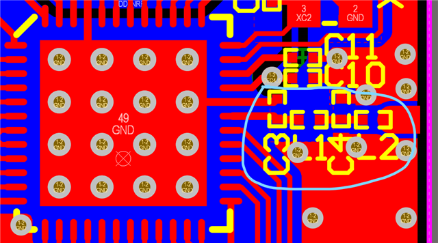
    The matching network for the radio output should be placed close to the SoC. A reference for how this should be done can be found in the nRF52840 reference layout, downloadable from here.

    The antenna's matching network should be placed as close as possible to the antenna. The idea is that both parts are matched to 50 ohms, and thus, can be connected through a 50-ohm transmission line and/or cable with minimal loss. The radio output matching network also has a filtering function for harmonics we want to suppress.

    Best regards,
    Mathias

Reply
  • Hi, Hampus.

    I am now wondering what the recommended connection between these boards would be? Initially I was planning on routing antenna through one trace on an FPC cable (since this is how the other signals will be passed between the boards), but after some reading it seems that a mini-coaxial cable would be preferred since this can be impedance matched to 50ohm.

    Yes, a type of coaxial cable is what you would need for this. Both due to impedance matching and shielding from outside noise and interference.

    Also where should the matching network be placed? On the antenna board, close to the antenna? Or close to the SoC IC?

    You will need two matching networks.

    The matching network for the radio output should be placed close to the SoC. A reference for how this should be done can be found in the nRF52840 reference layout, downloadable from here.

    The antenna's matching network should be placed as close as possible to the antenna. The idea is that both parts are matched to 50 ohms, and thus, can be connected through a 50-ohm transmission line and/or cable with minimal loss. The radio output matching network also has a filtering function for harmonics we want to suppress.

    Best regards,
    Mathias

Children
No Data
Related